Boost Me (for free)
Boost me for free to support my work
Boost
🧩 Gridfinity Drawer Baseplate – Description
A fully parametric Gridfinity baseplate designed to perfectly fit any drawer 📐

The baseplate is generated with millimeter-precise accuracy, ensuring a clean, gap-free result every time.
The alignment and positioning of the spacing / margins can be adjusted, allowing the Gridfinity pattern to be centered or aligned to any side of the drawer ↔️⬆️⬇️

The model automatically splits the baseplate to match your printer’s build plate size 🖨️
All parts can be assembled using integrated bottom X-connectors — no tools required 🔧❌

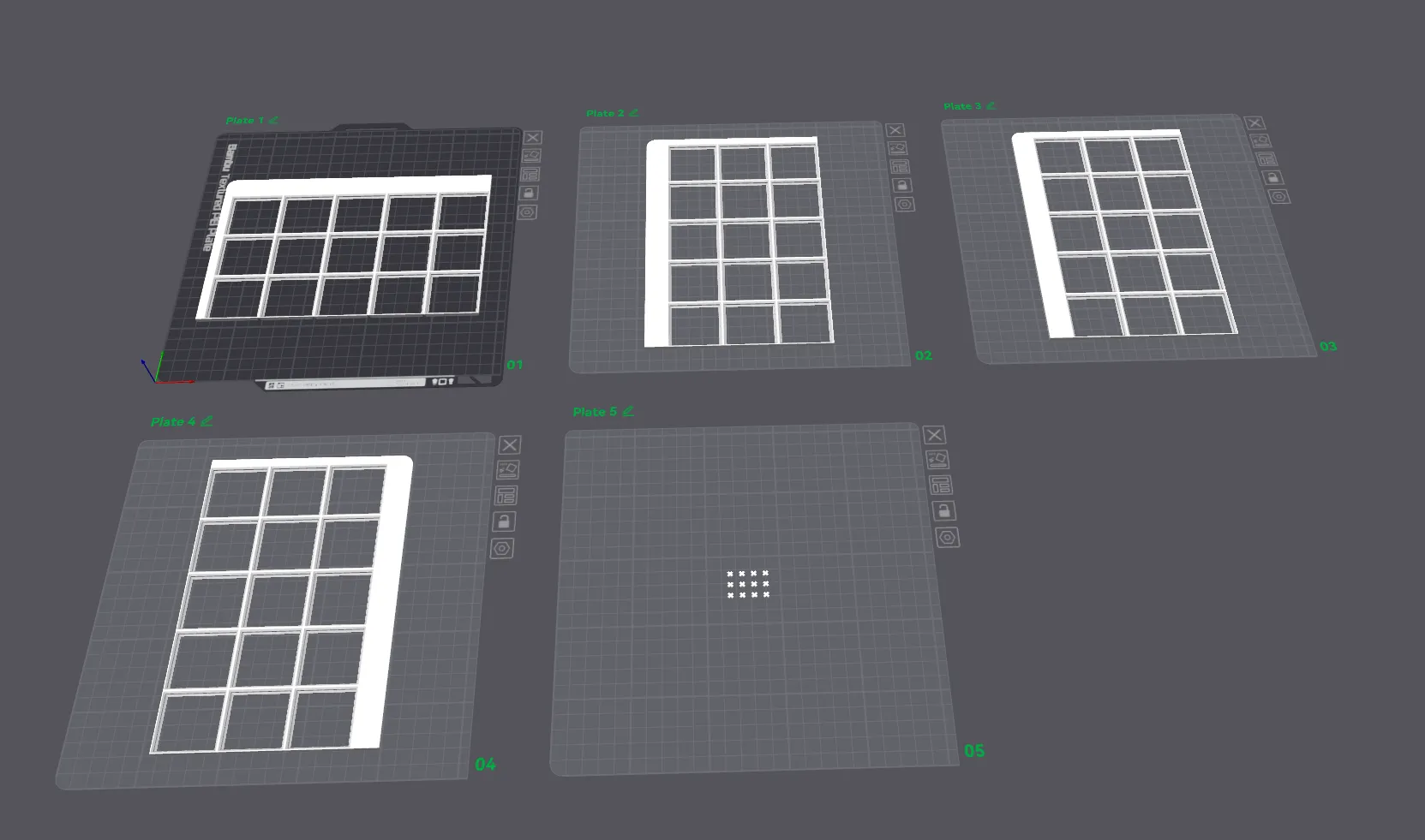
Each individual baseplate tile is automatically assigned to its own print plate, so everything is ready to print immediately after download 🚀
✨ Key Features
- 🧩 Fully customizable Gridfinity baseplate for any drawer
- 📏 Exact millimeter-precise fit
- ↔️ Adjustable alignment and spacing
- 📐 Two baseplate height options (standard & light)
- 🖨️ Automatic splitting to your printer’s build plate size
- ❌🔧 Tool-free assembly using bottom X-connectors
- 📄 One tile per print plate — no manual setup needed
- ⚡ Instantly ready to print after download
🛠️ Customization Guide
🔧 Target Size
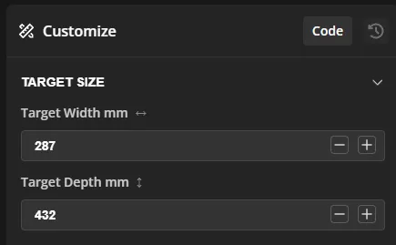
📐 Target Width (mm)
Defines the exact inner width of the drawer in millimeters.
- The Gridfinity baseplate will be generated to fit this width precisely
- The final model is adjusted to the millimeter, ensuring a tight and clean fit
- Measure the usable inner width of your drawer (not the outer size)
📐 Target Depth (mm)
Defines the exact inner depth of the drawer in millimeters.
- The baseplate will be generated to match this depth exactly
- Automatically adapts the Gridfinity grid to fill the available space
- Excess space is distributed based on the selected alignment options
⚠️ Important Notes
- Minimum size is one Gridfinity unit (42 × 42 mm)
- Sizes smaller than this will not generate a baseplate
- The baseplate is always aligned and split automatically after size calculation
🔧Base Frame Alignment
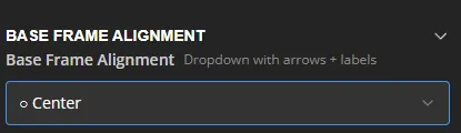
↔️ Base Frame Alignment
Defines how the Gridfinity baseplate is aligned within the available drawer space.
When the drawer size does not match an exact Gridfinity grid, the remaining space is distributed according to this setting.
You can choose to:
- Center the Gridfinity grid
- Align it to any edge or corner of the drawer
This allows you to control where the free space / margins are placed.
📍 Available Alignment Options
- ⬜ Center
Distributes the remaining space evenly on all sides. - ⬅️ Left / Right
Aligns the grid to the selected side, placing all extra space on the opposite side. - ⬆️ Top / Bottom
Aligns the grid to the selected edge of the drawer. - ↖️ ↗️ ↙️ ↘️ Corner Alignments
Aligns the grid to a specific corner, placing all remaining space on the opposite edges.
🔧 Baseplate Height
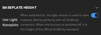
📐 Use Light Baseplate
Switches between two baseplate height versions.
- Enabled (Light Baseplate) 🌱
Uses a reduced-height, material-saving version of the Gridfinity baseplate
✔ Fully compatible with all Gridfinity containers
✔ Saves filament and reduces print time - Disabled (Standard / Zack Spec) 📏
Uses the official Gridfinity baseplate height
✔ Maximum rigidity
✔ Matches the original Gridfinity specification
💡 When to Use Which Version?
- Use Light Baseplate for most drawers and everyday storage
- Use Standard Baseplate if you need maximum strength or strict adherence to the original Gridfinity spec
🔧 Split Into Plates
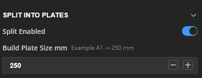
🧩 Split Enabled
Enables or disables automatic splitting of the Gridfinity baseplate.
- Enabled ✅
The baseplate is automatically split into multiple tiles to fit your printer’s build plate size.
This is recommended for large drawers or smaller printers. - Disabled ❌
The entire baseplate is generated as one single piece.
Only use this if the full baseplate fits on your printer’s build plate.
🖨️ Build Plate Size (mm)
Defines the maximum usable size of your printer’s build plate in millimeters.
- The model automatically calculates how many Gridfinity units fit on one plate
- The baseplate is split into balanced tiles that fit within this size
- Tiles are optimized to minimize seams and connectors
💡 Example:
- A1 size → 250 mm
- Bambu X1 / P1P / P1S → 256 mm usable area (recommended: 250 mm)
🔗 Assembly
- Split baseplates are connected using integrated bottom X-connectors
- No glue or tools required
- The assembled baseplate behaves like a single solid piece
🔧 X Connectors (Bottom)
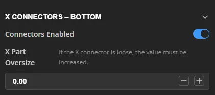
🔗 Connectors Enabled
Enables or disables the bottom X-connectors used to join split baseplate tiles.
- Enabled ✅
Bottom X-connectors are generated automatically and allow tool-free assembly of all baseplate tiles. - Disabled ❌
No connector pockets are generated.
Use this only if the baseplate is printed as a single piece.
❌➕ X Part Oversize
Adjusts the size of the printed X-connectors.
- Increasing this value makes the X-connectors slightly larger
- Helps achieve a tighter, more secure fit if the connectors feel loose
- Does not affect the size of the connector pockets
💡 Recommended values:
- 0.00 → Default fit
- +0.05 to +0.15 → Tighter fit for loose tolerances
🧠 Notes
- X-connectors are placed only at actual tile intersections
- The required number of X-connectors is calculated automatically
- No glue, screws, or tools are required for assembly
🔧 Generate X Parts
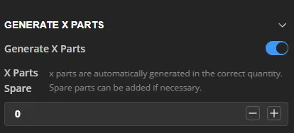
🧩 Generate X Parts
Controls whether the printable X-connectors are generated automatically.
- Enabled ✅
All required X-connectors are automatically generated in the exact quantity needed to assemble the split baseplate. - Disabled ❌
No X-connectors are generated.
Use this if you already have X-connectors or want to print them separately.
➕ X Parts Spare
Adds additional spare X-connectors on top of the automatically calculated amount.
- Useful in case of print failures or future adjustments
- Spare parts are placed on the X-parts print plate
- Does not affect the baseplate geometry
💡 Recommendation:
- 0 → Default (exact amount)
- +2 to +4 → Safe margin for spares
🧠 Notes
- The number of X-connectors always matches the actual connector pockets
- X-connectors are automatically arranged for efficient printing
- All X-parts are ready to print without any manual setup
🔧Rounded Corners
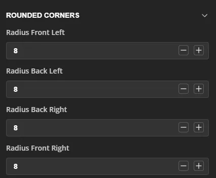
◢ Rounded Corners
Controls the corner radius of the outer baseplate edges.
Each corner can be adjusted independently, allowing the baseplate to fit drawers with rounded edges, fillets, or hardware constraints.
📐 Radius Front Left
Sets the corner radius for the front-left corner.
📐 Radius Back Left
Sets the corner radius for the back-left corner.
📐 Radius Back Right
Sets the corner radius for the back-right corner.
📐 Radius Front Right
Sets the corner radius for the front-right corner.
💡 Notes & Tips
- Radius values are specified in millimeters
- Set a radius to 0 for a sharp corner
- Use rounded corners to:
- Match the shape of the drawer
- Avoid interference with drawer hardware
- Improve the overall visual appearance
🧠 Recommendation
Most drawers work well with a radius between 5–10 mm.
Adjust as needed to perfectly match your drawer’s inner geometry.
💬 Feedback & Future Improvements
This model is actively developed and open for future improvements and new features.
If you have ideas, suggestions, or special requirements, feel free to leave a comment — feedback is always welcome and helps improve the model for everyone.
If you find this model useful, a Boost on MakerWorld 🚀 would be greatly appreciated and helps support further development.
Thank you for your support and happy printing! 😊