Just finished up my prototype for QR clock 2.0!
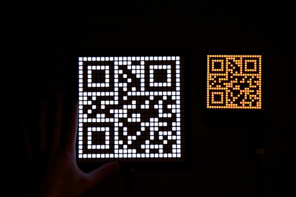
New and Improved
After the success and popularity of my original QR Clock, I decided it might be a fun challenge to redesign the clock into a more attractive and lower-cost form factor. The end goal is to make this the flagship product that gets my Ch00ftech Store on its feet. Before I could start worrying about manufacturing and shipping, I needed a new prototype, so this post is to tell you about what I’ve changed.
I addressed a number of mechanical and electrical problems that I had with the original design, but this time around, I’ve also addressed some of the pricing and supply chain issues I had before. This clock is actually much cheaper to make than the original, and getting it that way involved some new experiences for me.
Mechanicals
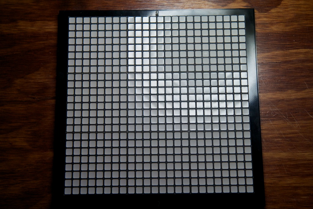
The new clock’s PCB is an 8×8 inch square that doesn’t have the unattractive mess at the bottom like the old model. The board was again printed at Myro and only cost  7 a piece and with 9 of them per unit, I was looking at one hell of a BOM cost for something I was hoping to sell for a reasonable price.
My first thought (hinted at in the last post) was to purchase some displays from Futurlec, a shop I hadn’t considered before. They had square-pixel white displays for almost half the price of the bi-color displays I was using. Single units ran  3.30/ea for an order of 1000. They also had some colored displays for even less. I really liked the fact that all of the colored displays had the same pinout leaving some options for interchangeability, but I was disappointed to find that the white displays had a different pinout which would require a unique PCB.
I ordered a handful of each, but for some reason my order didn’t ship right away. After waiting a week with no tracking number, I emailed them and learned that the colored displays had a lead time of “1-2 months”. Impatient, I decided to drop the colored displays, and just work with the white ones.
I received the white ones and was really pleased with how they looked when lit up:

However, when shutoff, they had a really terrible yellow color:

White LEDs are actually just blue LEDs with a yellow fluorescent coating which together make white. Most displays will be just a housing for a self-contained white LED, but these guys must have decided to move the yellow coating to the outside where it can be easily seen.
Deciding that the displays weren’t good enough, and running out of shops to search through online, I decided to do something I had never done before:
Shopping on Alibaba
Alibaba.com is a website you’ve probably stumbled upon when it showed up in the search results for something you were shopping for. It’s not really an online store, but rather a place for conducting trade. Manufacturers will post listings for products they make, and buyers can contact the manufacturer if they’re interested in making a purchase.
You can seriously find anything on this site from a hunting raptor costume to a Pringle can vending machine. The real catch is that most things on the site have a minimum order quantity. For example, that Pringle machine has a minimum order quantity of 50.
Now one thing that really sets Alibaba apart from other shops is that nothing is set in stone. Prices, quantities, and even product features are negotiable. The listed prices are usually just estimates, and “sample” orders can be placed below the minimum order limit. The only way to find out for sure is to contact the seller and ask some questions.
Communicating with humans over the internet can be kind of scary. I was lucky to have some experience contacting foreign vendors through my professional work. The key is to keep your sentences short and to try not to use any pronouns. It’s okay to be short and blunt; any affectation will only serve to strengthen the language barrier. You typically just need to provide a quantity and a shipment location and ask for a price. I found a seller that looked like they might have what I was looking for, and struck up a conversation:
Hello,
I am interested in the LED matrix part no. XL23884UR-ABC/W in Red, Yellow, and Green diffused. Please provide a quote for quantities 100, 250, 500 for delivery to Seattle, WA, USA.
Regards,
~Michael
And I quickly got a reply from “Dayla”
Dear Mr. Michael Ciuffo,
Thanks for your inquiry.
For your request,please find the following information:
1.About the led dot matrix,you need common anode or common cathode? you need white diffused one,right?
2.For green color,we have yellow-green and pure green,which one do you prefer?
3.Do you have any special requirement for the circuit?if yes,please send me your circuit for my reference, if no,we’ll use our common circuit.
Please confirm the above information,so that I can give you the right price.
If you have any question,please don’t hesitate to ask me.
Have a nice day!
Thanks and best regards,
Dayla Deng
After a bit of a back and forth, I decided to order a handful of their displays. I asked for 10 red, 10 green, and 10 amber displays in both clear and diffused varieties. They provided this invoice:

If you look closely, you’ll see “Western Union”. If you know anything about the internet, it’s that you’re not supposed to wire people you don’t know money over Western Union. In reality, I believe Alibaba is a pretty safe place, but I’ll only recommend transferring money that you can afford to never see again.
So I wired her the money and awaited my package. Three weeks later, this landed on my door step:
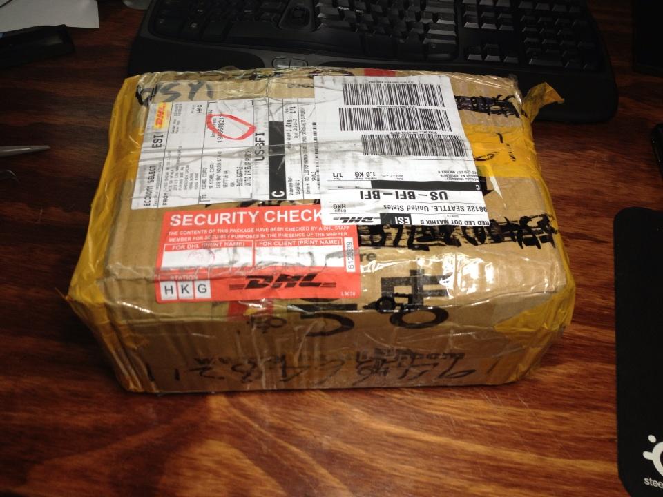
One wonders if they tried to make it look sketchy. There’s something about the Chinese people and packing tape. I’ve been over there and seen them just fold cardboard and laminate it in tape calling it a “box”. Regardless, they are clearly masters of their craft as my displays all showed up in one piece:
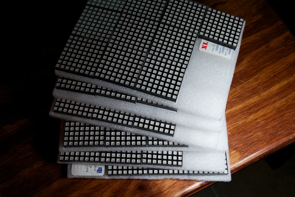
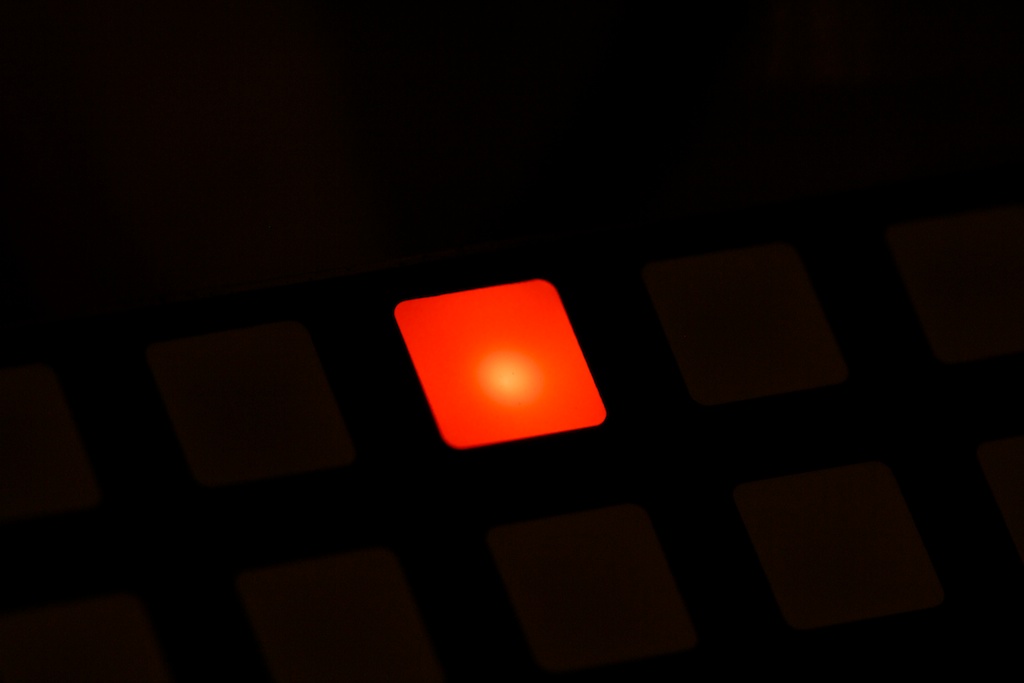
You can see that some of these displays are the clear variety where the LED is visible behind the matrix’s lens. After firing them up, I noticed that even the diffuse ones weren’t that diffuse as the LED in the center of each pixel was clearly brighter than the edges :
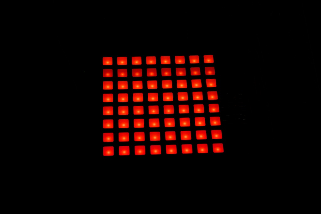
It’s even more obvious in a closeup:
Furthermore, a number of the displays had some cosmetic damage on the edges. It looked like they got beat up and then someone actually went back with a Sharpie to try to cover it up:

The diffused and clear displays were basically exactly the same part except the diffuse ones were filled with a more opaque plastic. This did a little to diffuse the LED light, but it did a lot to completely obscure the information on the bottom of the display:
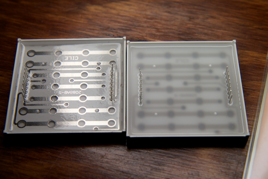
I was concerned that whoever was going to assemble my clocks would have no idea which way the displays went in.
I sent an email to Dayla bringing up my concerns. She replied with this:
Hi Michael,
Thanks for your feedback and for your request,please find the following information:
1.Because the white diffused led dot matrix added diffusion,so you can’t see the markings,
sorry for my carelessness,now please find the attached picture .
2.For the “hot spot” in the center,it’s very normal,dear,since there is a led inside, if thicken the lens,the dot will bulge out of the matrix display,so it’s impracticable,
but we can add more diffusion next time if you need,so that the hot spot will be not so obviously,but the matrix display won’t be so bright as before.
If you still have any question,please feel free to ask me.
Have a nice day!
Thanks and best regards,
Dayla
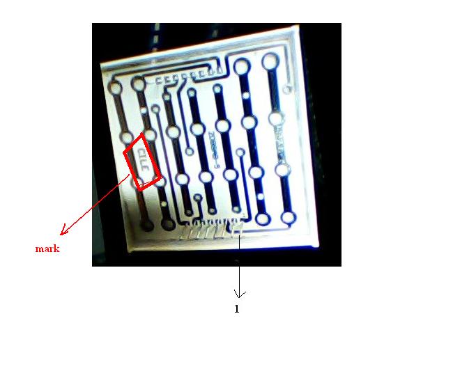
I explained that while I had no trouble orienting the displays, the operator assembling the unit would. She replied back telling me that they would be marking the next shipment like so:
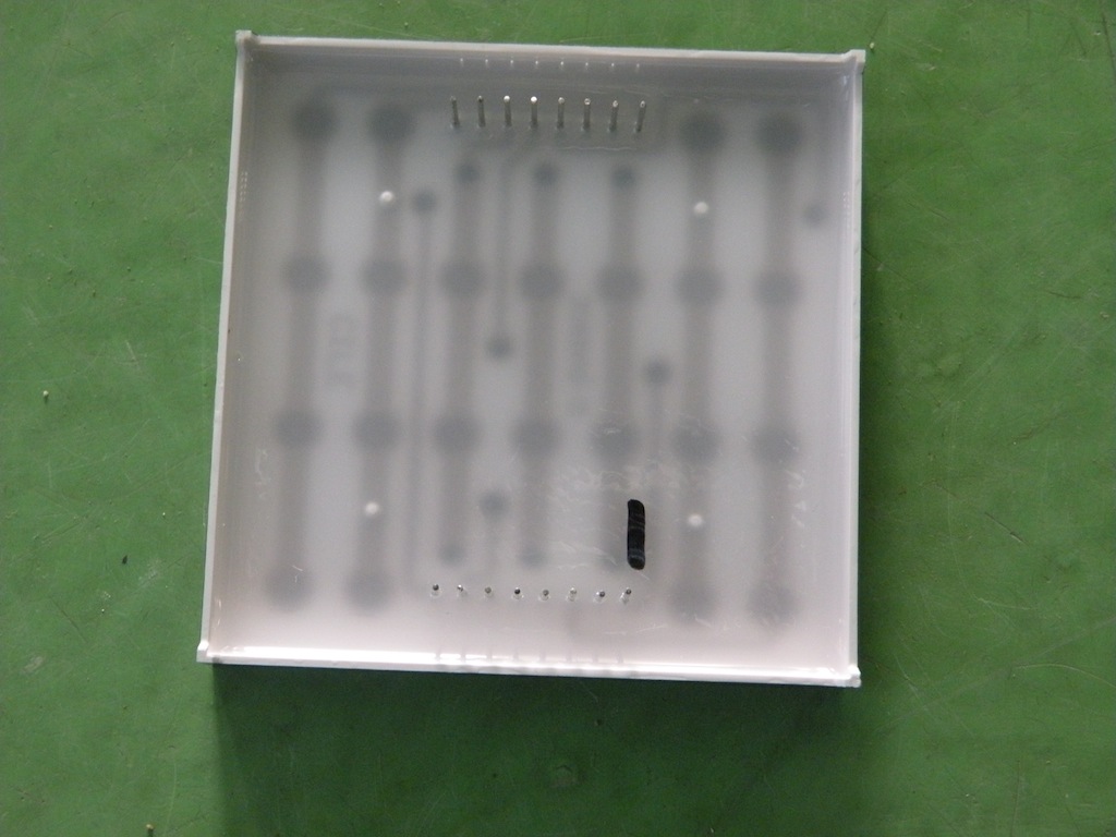
These guys really love their Sharpies…
I asked about potentially ramping up the level of diffusion in the display, but she told me that the minimum order quantity for a custom plastic was 1000, but I could get samples at 1.5x the normal cost.
I was feeling a little iffy about this order, but my indecisiveness ended when I thought to test all of the displays. Of the sixty displays I received, one of them did this:
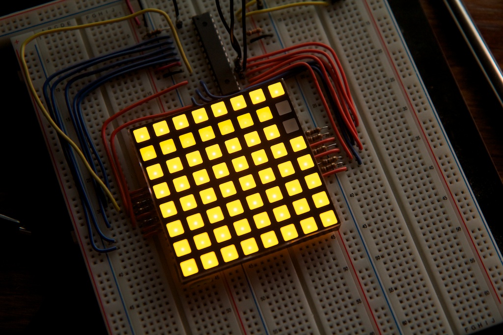
I brought this up and got this in return:
For the problem in the first picture,please check whether it’s empty solder or not,
and you should also check whether it’s connected well or not…
Assuring her that there were no solder (in this case breadboard) issues, I got this as a reply:
If you’ve checked and the problem still haven’t solved,dear,I’m also very confused,
because I’ve never received any problem from my customers for our dot matrix since so many years.
Yeah… it was time to look for a new vendor, but I have to give her credit for her persistence. After I had pretty much decided to move on, I still got a warm Holiday greeting:

As well as an…unprovoked gchat conversation about a month after I stopped talking to her:
Dayla: Hi,Michael
6:37 PM me: um…hi who is this?
Dayla: Dayla here
me: Oh, hello.
6:38 PM Dayla: Hi,how are you these days?
me: I am well.
6:39 PM Dayla: Very good,do you have holiday for the new year?
me: Yes
Dayla: Wow,great.
6:41 PM So are you come back to work now?
me: I am
6:43 PM Dayla: Michael,I wonder how is our dot matrix?
me: I am sorry, but I have decided to use another manufacturer
6:44 PM Dayla: Why?
me: They offer a higher quality display at similar price. The light is more even on the LEDs.
6:46 PM Dayla: Dear,but I t’ve told you that wthat you mentioned is not the quality problem,it’s can be solve.
6:47 PM And for the price,if you buy 1000pcs next time,we can give you some discount.
6:48 PM me: They also have better markings and larger LEDs
6:50 PM Dayla: Better?But I also promised that we can meet your demand next time,don’t you believe me?
me: I’m sorry Dayla. I have made up my mind.
6:53 PM Dayla: Ok,hope to cooperate with you in the future.
I did find another vendor, and carried out a similar conversation ending with me ordering 10 white and 10 amber LED displays. The whites ran  1.13.
1.13.
These were from “SHENZHEN LIANG JIA LIANG TECHNOLOGY CO., LTD” and were much better made including both printing to indicate orientation as well as better diffusion:

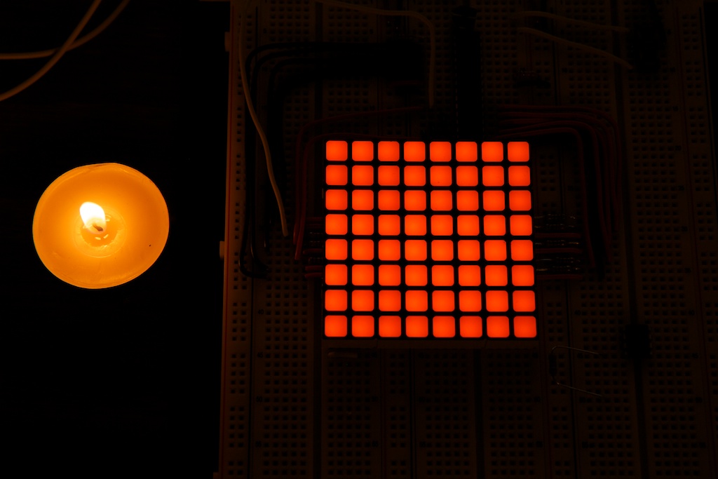
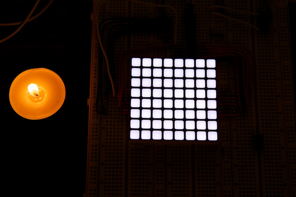
The amber looked pretty slick, but the white was much brighter especially considering that they were being driven at the same voltage and the white has a higher
![\[V_F\]](https://ch00ftech.com/wp-content/ql-cache/quicklatex.com-f2e969181441d53e1aa97332e1ef9124_l3.svg "Rendered by QuickLaTeX.com")
. The datasheet lists the “Ultra Amber” display at 100mcd while the white sits at 180-200, so it makes sense. The good news is that these displays are pin compatible, so if I decide to change the color, it’s an easy change.
The edges also contained some little grooves to help line up displays used to make a larger matrix. I was a little off-put by the markings because some of them will be visible to the end-user, but I figure it’s something I’ll probably just have to deal with.
The displays arrived in fairly good condition although one of them was a little busted up:

And a number of them had what looked like a thin layer of epoxy on the sides that prevented them from fitting together very well. It was fairly easy to remove with a razor blade. I’m not terribly concerned about these issues. I will be ordering the displays and then packing them up and shipping them out to whatever assembly house I use, so I’ll have a chance to inspect them personally. I can comb out the few that have issues.
I think I’m pretty much settled on this vendor. They offer quality displays at a reasonable price, and they can even offer a discount for orders over 1000.
Settled on a display, it was time to update my schematic and layout.
Electrical Changes

There were a few small fixes that I needed to patch up some mistakes I made with the original design. As mentioned before, all of the vias are now covered. I also added a substantial amount of bypass capacitance to the power rail using a handful of surface mount 100
![\[\mu\]](https://ch00ftech.com/wp-content/ql-cache/quicklatex.com-bee17ce5c29d6fa9fa02b47a477d5c06_l3.svg "Rendered by QuickLaTeX.com")
F capacitors.
The clock line for the programmer and shift register bank are now split so the display doesn’t go nuts when programming. To prevent random flashing during startup, I added a pullup resistor to the output enable line to ensure that the display is dark as the software is initializing.
Confident that my code would keep me from driving my LEDs at a 100% duty cycle, I lowered the current-limiting resistance down to 62
![\[\Omega\]](https://ch00ftech.com/wp-content/ql-cache/quicklatex.com-5060d7d946cd178c2e892e089190f3ff_l3.svg "Rendered by QuickLaTeX.com")
to make the display brighter at the cost of temporarily overdriving the LEDs.
The ordering of the shift registers’ outputs was changed slightly to favor a neater layout over neater code.
Previously, I had used a 32.768kHz oscillator as there are a bunch specifically designed for use in clocks. What I didn’t realize is that the major benefit of a low-frequency oscillator like that is its low power consumption which is very useful for portable devices like wrist watches.
Since the clock was going to be plugged in anyway, I reasoned that I could ditch it for a more conventional higher frequency crystal. Rather than clocking asynchronously, this new 11.0592MHz oscillator drives the system clock (replacing the 8MHz internal oscillator) which drives the real-time clock.
The 11.0592MHz system clock also provides the benefit of being generally faster than 8MHz which allows me to increase the refresh rate. It’s more stable than the internal oscillator and enables serial communication over the RX/TX lines should I chose to use that at some point in the future.
Strangely, after soldering the new clock together and updating my code, I found that the clock was keeping really lousy time. It was running at almost half the rate I expected. I first suspected something was wrong with my code, but under closer scrutiny, I still couldn’t find anything.
My oscilloscope is too slow to probe an 11MHz signal, but I could probe the output enable line which should oscillate at 1/256th of the system clock. What I found was surprising. It was oscillating somewhere around 32kHz. Curious, I did the math and worked out that 32kHz*256 = 8.192MHz. Looking closer at my oscillator, I saw this:
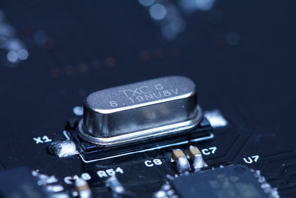
I had originally assumed that the markings on the crystal were meaningless production codes, but the 8.19 was pretty damning evidence that this wasn’t an 11.0592MHz oscillator.
I double checked the packing slip and even the bag label, but all of those read 11MHz:

Apparently, someone at Digikey meant to grab some 11MHz oscillators, but grabbed some 8MHz ones instead. This kind of thing has happened to me before, and Digikey is usually very helpful. I’ve sent them an email about it, and expect a response shortly.
For the time being, the clock is currently running at 8.192MHz with code adjusted to accommodate. This is only slightly faster than the part’s internal oscillator, so I can’t do much to increase the refresh rate at the moment.
Software Changes
Because I ditched the low-frequency oscillator, I had to change around what each timer does:
Timer1 is now used to keep real time. I can only divide the 11MHz system clock by 1024 which still leaves me with a 10.8kHz interrupt which will overflow an 8-bit timer 42 times a second. Handling this overflow that often would steal too many cycles from other important tasks.
Fortunately, Timer1 is a 16 bit timer, so I can simply have it count up to any number between 1 and 65,535 (for the time being, it’s actually counting to 8000 instead of 10,800 to accommodate the 8MHz crystal).
Timer2 is now taking over Timer1’s original functions handling screen refresh.
The hardest part of updating the software was remapping the display. A number of dramatic changes were made to the LED ordering, so I had to adjust the code appropriately. This took longer than expected because my original design kept the LEDs pretty much in order while my new one had them all jumbled up to improve layout efficiency. Most of my time was spent looking for my original output conversion routine only to realize that I didn’t need one before!
I did come across one bug that actually exists in the original clock. I found that part of my new clock arbitrarily had a line drawn through it. This line wasn’t persistent on every power up though. Occasionally, the line would only reach part way through the clock while other times it was gone altogether.
It turns out that part of my code was pulling values from past the end of an array. It just so happened in the original clock that that block of code was always empty, but apparently with the new hardware and slightly different software of the new clock, those registers would occasionally be full. I put a bandaid on the problem for now, but I’ll probably be re-writing the whole thing to tidy up at some point soon.
Self-Criticism
This is the first project I’ve ever designed to be sold, so I’ve tried to be as critical as possible regarding its appearance. While I think in general, the clock looks pretty good, there are a few bits that are really bugging me.
The displays look good, but they still have their part number stamped on the outside. This means that the rather unattractive part numbers are stamped along the right side of the otherwise featureless clock.
Thanks to a tip from Patrick down in the comments section, it looks like I can easily dispatch the numbers stamped on the displays using a dab of acetone. It comes off really easily!
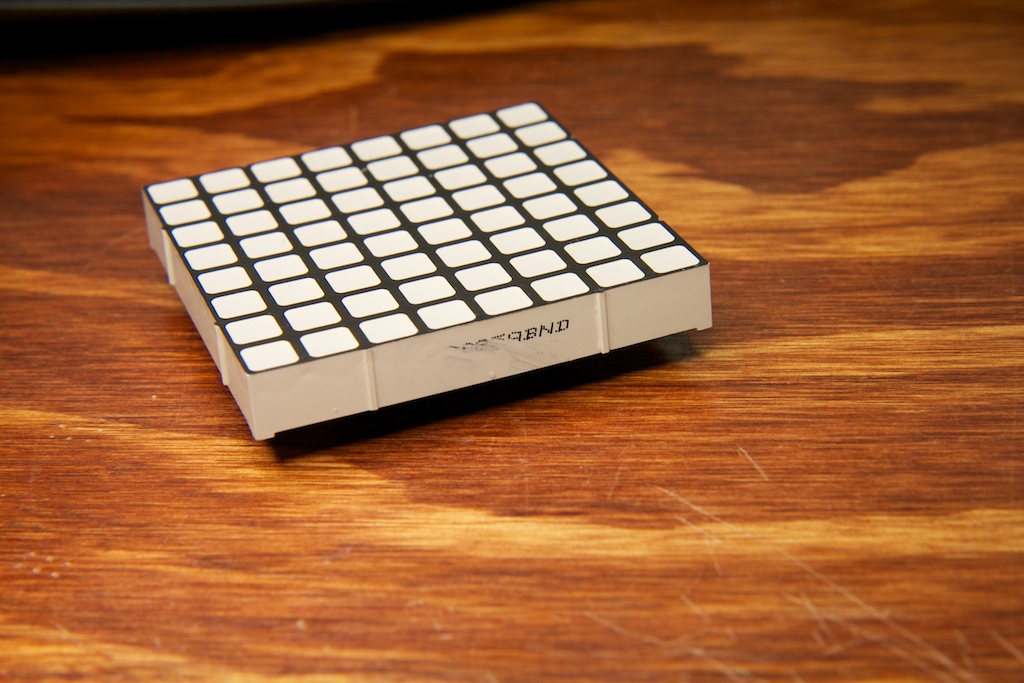
Also, the display is 24×24 while I really need 23×23. This leaves an unused column and row, and it places the QR code off-center. I’m still trying to figure out what I can do with the extra pixels to make the display look better. I was considering trying to get it to count seconds, but with 47 pixels, that’s not enough to make up a whole minute. Filling it in solid could work, but that makes the clock look especially uneven in the dark (where it arguably looks cooler in general). If you have any suggestions, let me know.
This could all be resolved by making my own LED matrix, but with the pricing as great as it is on these, I just don’t think I’ll be able to design a matrix cheap enough that does the job nearly as well.
I think the current strategy is to market the project as a combination QR clock and hobbyist LED matrix display. I might even make some custom firmwares that allow the display to be controlled easily over the serial port.
Regardless, the clock still looks pretty darn neat up on a wall.
Moving Forward
Now that I have my prototype, I’m going to try to raise some money and get some of these dudes made. I’ve never been a huge fan of Kickstarter, but Tindie looks like a pretty good option. Unlike Kickstarter, TIndie is a store, and they support pre-ordering rather than “backing”.
With the funds, I’ll probably be looking at Myro to do both my PCB printing and assembly. I’ve never worked with an assembly house before, so I’m not entirely sure what that’s going to be like. They list lead times on their site, but I’m sure that doesn’t take into account shipping time. Besides, I need to order the displays first, and that takes at least three weeks by itself.
I might actually try installing the displays myself. I’m concerned that Myro might be really good at soldering components, but not so good with cosmetics. I’d be pretty torn up if I got back an order of 50 clocks with super uneven LED modules.
I timed myself when I was assembling this clock. The surface mount components took me about 1.5 hours to install, but the displays only took 20 minutes. Though, this was after the displays had already been inserted once and had their pins straightened.
Another benefit of doing it myself would be the ability to change the color of the clock on a order-by-order basis. I might even sell the clock with the displays unsoldered at a discount for DIYers.
I just really want to turn this into a turn-key operation, so I’d like to do as little of the assembly myself as possible.
I also need to source a good AC adapter. The one I’m using right now is from an ebay seller who can provide large quantities, but the cable length is only 3 feet which isn’t very suitable for a wall clock.
Update: A reddit user suggested using micro-usb instead of a DC barrel jack. There are tons of options for high-current phone chargers that could be used to power it, and the connector itself is very low profile. I’m going to be looking into it for the next revision.
A quick price estimate puts the parts/assembly cost of the clock somewhere around  100. I hope that isn’t too much.
Right now, it’s all an issue of timing. I’m going to be out of town a substantial amount over the next six weeks, and even if I wasn’t, it’s going to take a while to make these things happen.
I might be drafting my Tindie fundraising campaign at some point in the next few days, but I’m hesitant to launch it too soon. I’ll have to see how far I can stretch my delivery date promise. Would you be willing to wait six months to receive your QR clock?
Also, do you have any feature requests? Is $100 a fair price for you?