Archive for the ‘Switchless Mods’ Category
Sega Master System 1 switchless mod
Montag, Oktober 25th, 2010
Today I have to make a switchless mod for the good old Mastersystem in its original form.
No problem for me, after changing sebs code for Mastersystems few months ago.
After opening you have to go under the mainboard and cut 3 wires of the mainboard
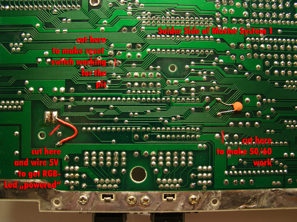
The parts site is holding the pic as usual
I am using the same code I done for the mastersytem2
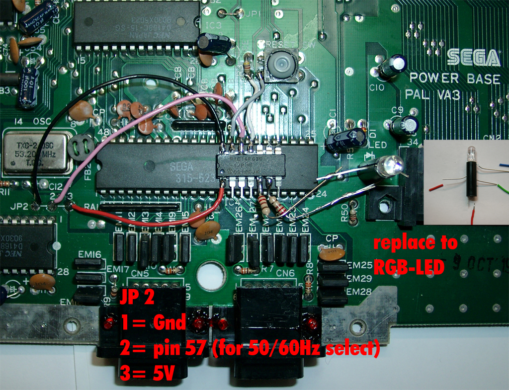
You have to remove the original 5mm LED and replace it with a RGB-Led with common plus like this one.
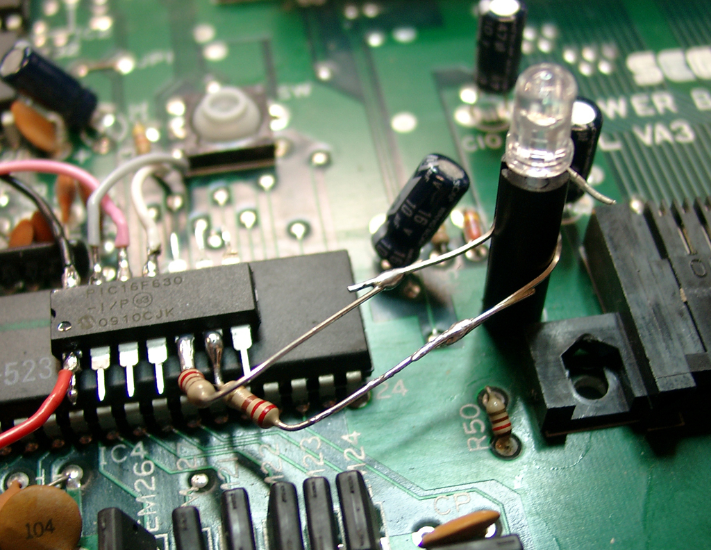
The resistors of the LED: 220Ohm. You can use higher ones, if the light is to bright.
Usage:
You can change the Modes via pressing the reset Button of the Mastersystem
If you press the reset button very short -> The Sega Console will do a reset
If you press the reset button longer the Led toggles between red and green.
If you let the button go at red the Mastersystem is set to 60Hz
If you let the button go at green the Mastersystem is set to 50Hz
Video:
Posted in Sega, Switchless Mods | Kommentare deaktiviert
SNES CIC switchless Mod at a USA/japanese SNES
Montag, Juni 14th, 2010
Thanks to Maximilian Rehkopf alias ikari_01 we can proudly present a new switchless Mod for the SNES.
Today I am using a japanese SNES. It works with a USA SNES too. It has the same layout.
Here you can find more information:
http://www.circuit-board.de/forum/viewtopic.php?f=21&t=1896&start=63 (german)
http://nesdev.parodius.com/bbs/viewtopic.php?p=61236#61236 (english)
The mod is using a PIC 16F630 with the following code: supercic
There are two ways to get the new CIC working.
a) with original CIC still onboard
To get the supercic working you have to lift the following pins of the original CIC.
Pin 1,2,10 and 11
b) removing the original CIC and add a 10k from Pin 8 to GND.
I will make use of way b) here:
Remove the original CIC (here you can see some pictures of a PAL SNES.
Its the same at the japanese/USA SNES.
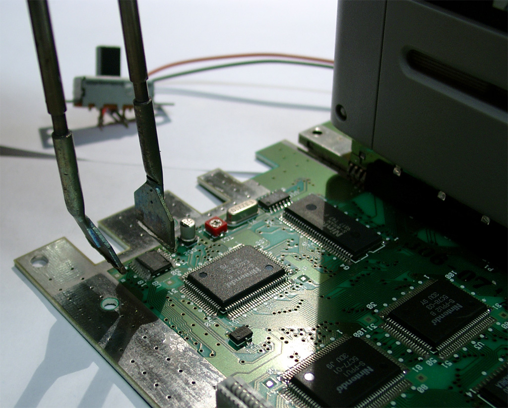
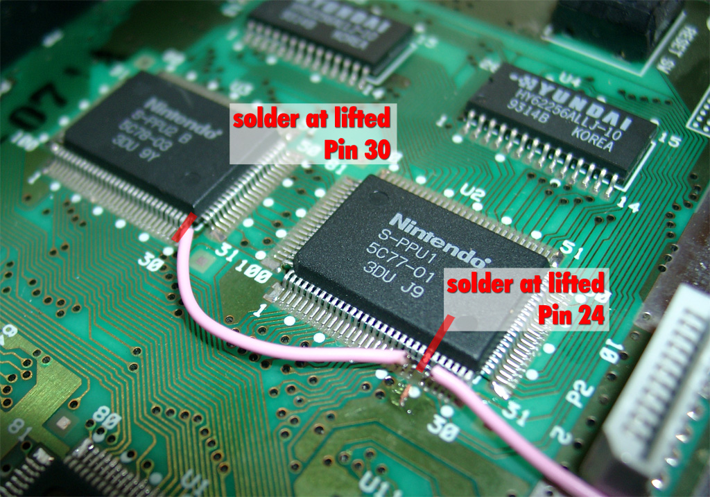
The usual 50/60Hz Pins:
You have to lift PPU2 Pin 30 and lift PPU1 Pin 24 and wire it together to Pin 12 @Pic12f630.
The Console is set to 60Hz if you set both Pins to GND
The Console is set to 50Hz if you set both Pins to 5V
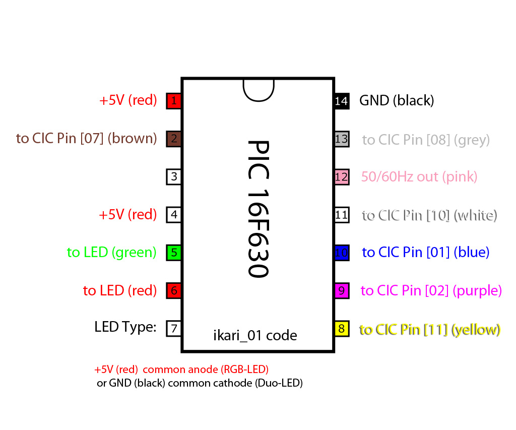
Here you can see the wiring of the pic with ikari_01 Code:
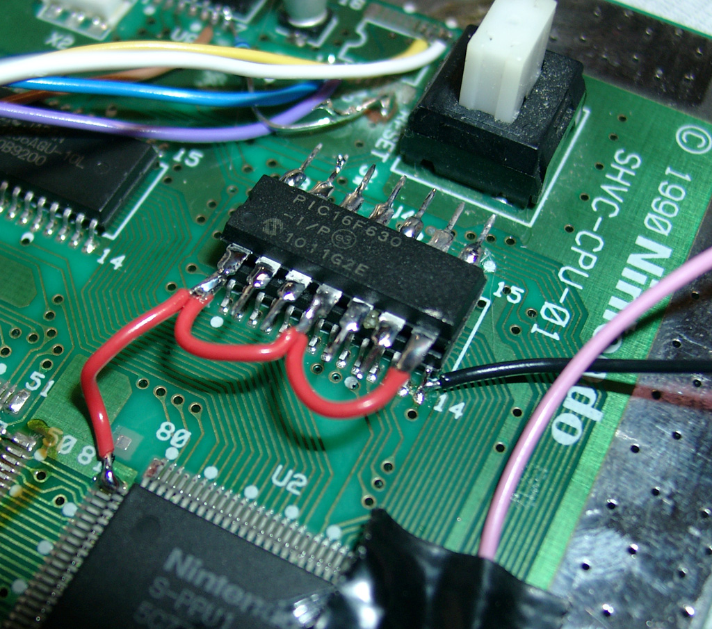
First we have to put some 5V at the PIC.
You can set the PIC into 2 Modes
a) Pin 4 to 5V (I used this Mode, see the red wire)
b) Pin 4 to GND
And please set Pin 7 To 5V (PIC is set to RGB-LED Mode (common anode).
Take 5V From the Pin 81 of the nearby IC
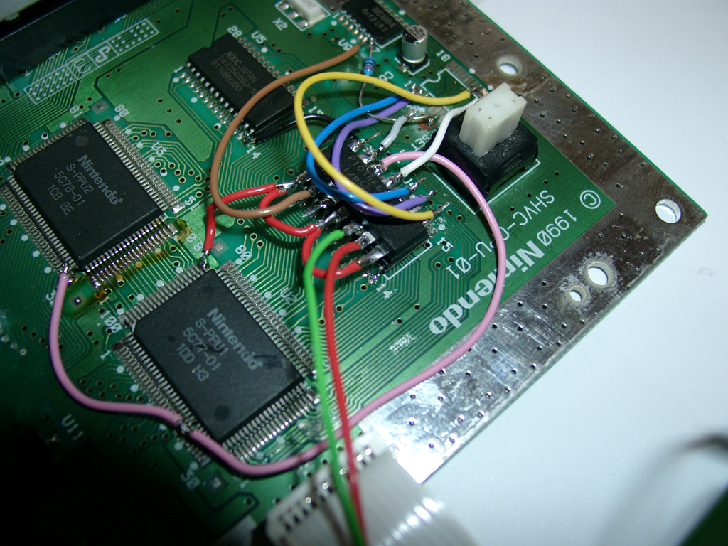
some pictures of more wiring
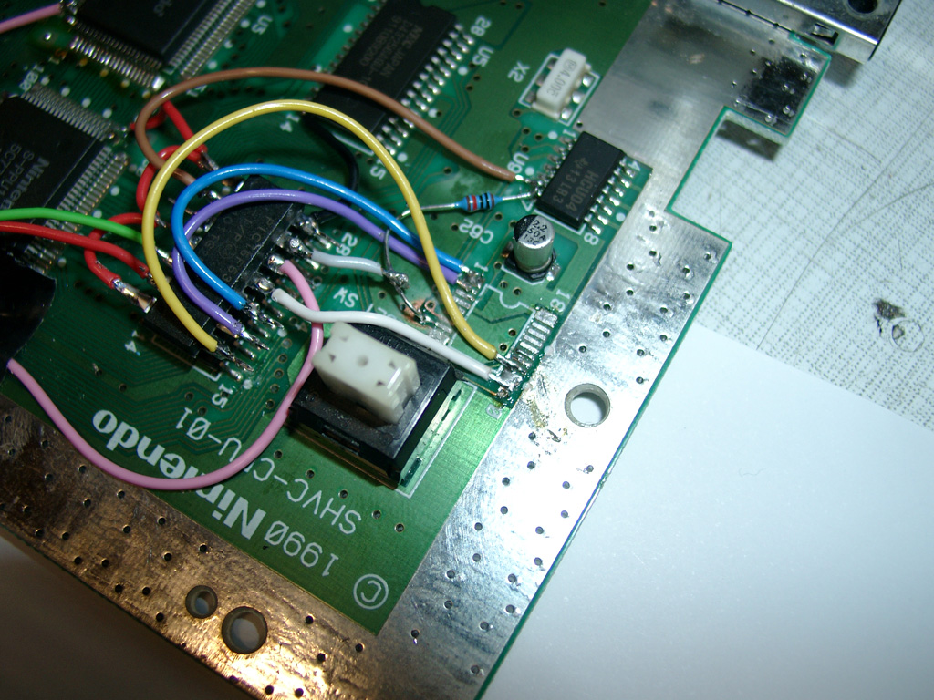
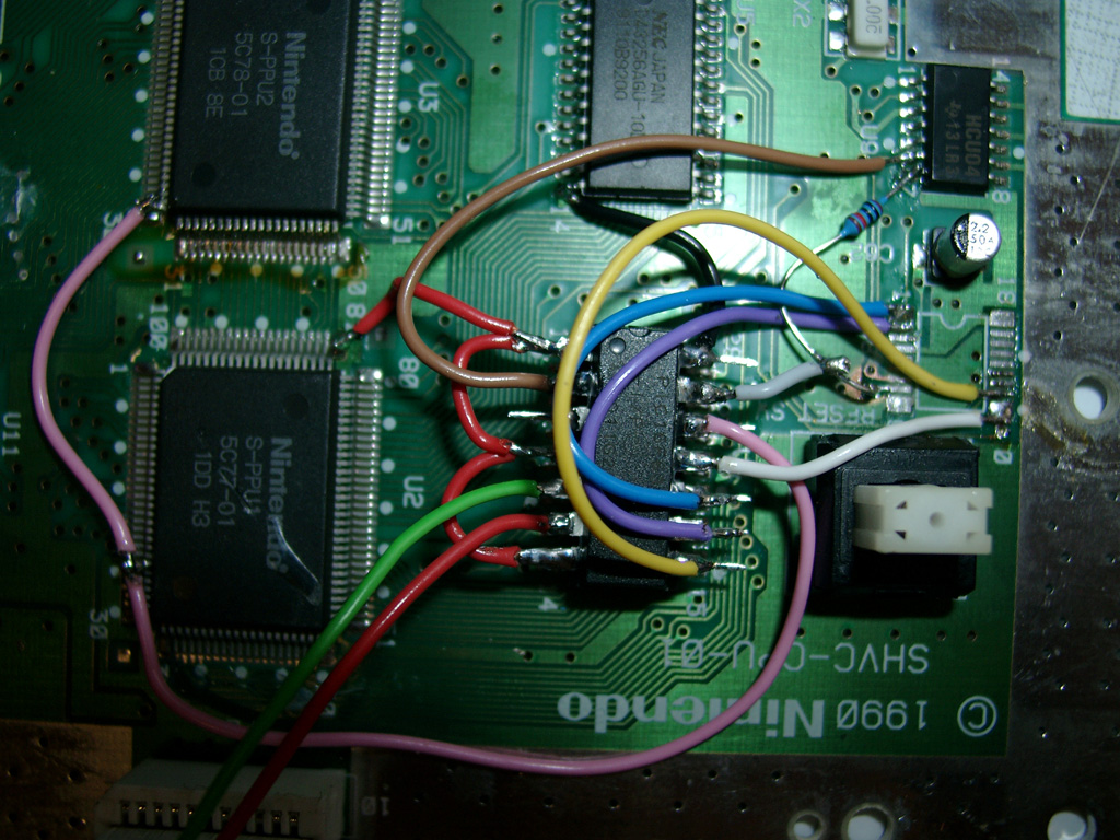
To do the LED Mod you have to remove the original LED at the controller port.
You can shortcut the original Resistor of the LED, if you want the full power of the RGB-LED 
With a RGB Led you can choose 2 of the 3 colors you wish. I am using the normal colors red and green.
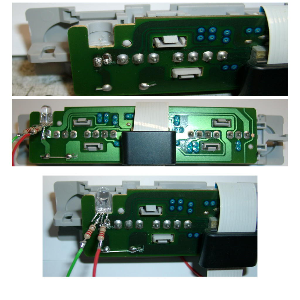
You can use two different LEDs:
a) a Duo-Led with common cathode (GND)
You have to set Pin 7 of the PIC16F630 to GND
b) a RGB-Led with common anode (plus)
Look here for a picture:
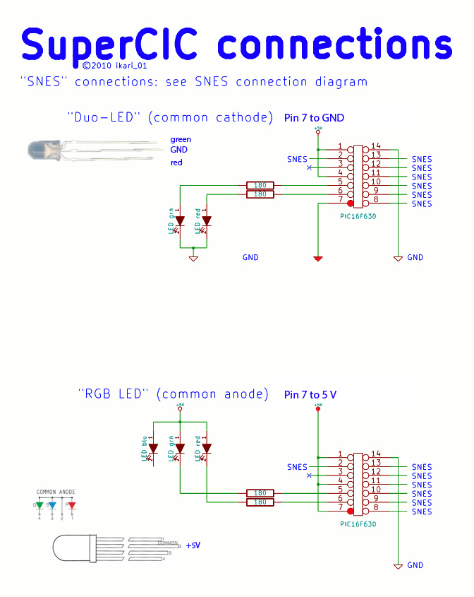
Some Info about the usage of the superCIC.
You can change between 50/60Hz and Auto Function by pressing the Reset Button for longer as around 0,5 sec. The current Status is shown by the DUO-LED. (red=60Hz, green 50Hz, orange=Auto).
After releasing the Reset Button the mode will be active. The SNES will not reset at this moment.
a) 50Hz Mode is active (green)
If you insert a PAL-Game, it will start with 50Hz
If you insert a NTSC-Game, it will start with 50Hz (if Pin 4 is set GND)
If you insert a NTSC-Game, it will start with 60Hz and switches to 50Hz after 9 sec. (if Pin 4 is set 5V)
If you insert a Game without CIC, it will start with 50Hz
b) 60Hz Mode is actice (red)
If you insert a NTSC-Game, it will start with 60Hz
If you insert a PAL-Game, it will start with 60Hz (if Pin 4 is set GND)
If you insert a PAL-Game, it will start with 50Hz and switches to 60Hz after 9 sec. (if Pin 4 is set 5V)
If you insert a Game without CIC, it will start with 60Hz
c) Auto Mode is actice (orange)
starting the Game in its native frequence.
If you insert a NTSC-Game, it will start with 60Hz
If you insert a PAL-Game, it will start with 50Hz
If you insert a Game without CIC, it will start with 60Hz
Here you can see a video, how the switching is working:
Here you can see a US-Unit with a RGB Led using blau and red part of the LED:
Posted in Nintendo, Switchless Mods | No Comments »
Sega Mega Drive 1 switchles mod
Montag, Juni 14th, 2010
Today I got a PAL SMD1 Console. I tried sebs code as several times before to make a switchless mod.
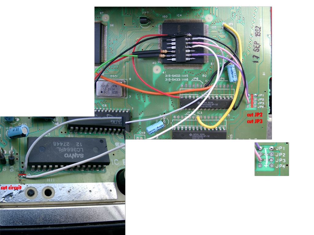
You have to cut 3 circuits and need a 3mm Duo-Led for displaying.
Posted in Sega, Switchless Mods | No Comments »
SuperCIC SNES switchless MOD (PAL)
Montag, Mai 10th, 2010
Thanks to Maximilian Rehkopf alias ikari_01 we can proudly present a new switchless Mod for the SNES.
I done the first modification at a PAL SNES, but it should work on US and japanese SNES too.
Here you can find more information:
http://www.circuit-board.de/forum/viewtopic.php?f=21&t=1896&start=63 (german)
http://nesdev.parodius.com/bbs/viewtopic.php?p=61236#61236 (english)
The mod is using a PIC 16F630 with the following code: supercic
Sorry the Code here is a newer version, so you have to set PIN 7 of the PIC 16F630 to GND. As here is described with a common cathode DUAL-LED!
There are two ways to get the new CIC working.
a) with original CIC still onboard
To get the supercic working you have to lift the following pins of the original CIC.
Pin 1,2,10 and 11
b) removing the original CIC and add a 10k from Pin 8 to GND.
The following pictures will show way b).
Here you can see a PAL SNES with the F413A CIC
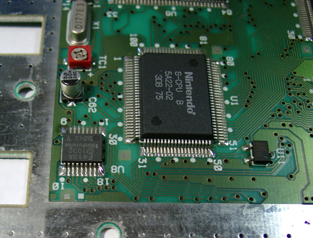
Removing the CIC
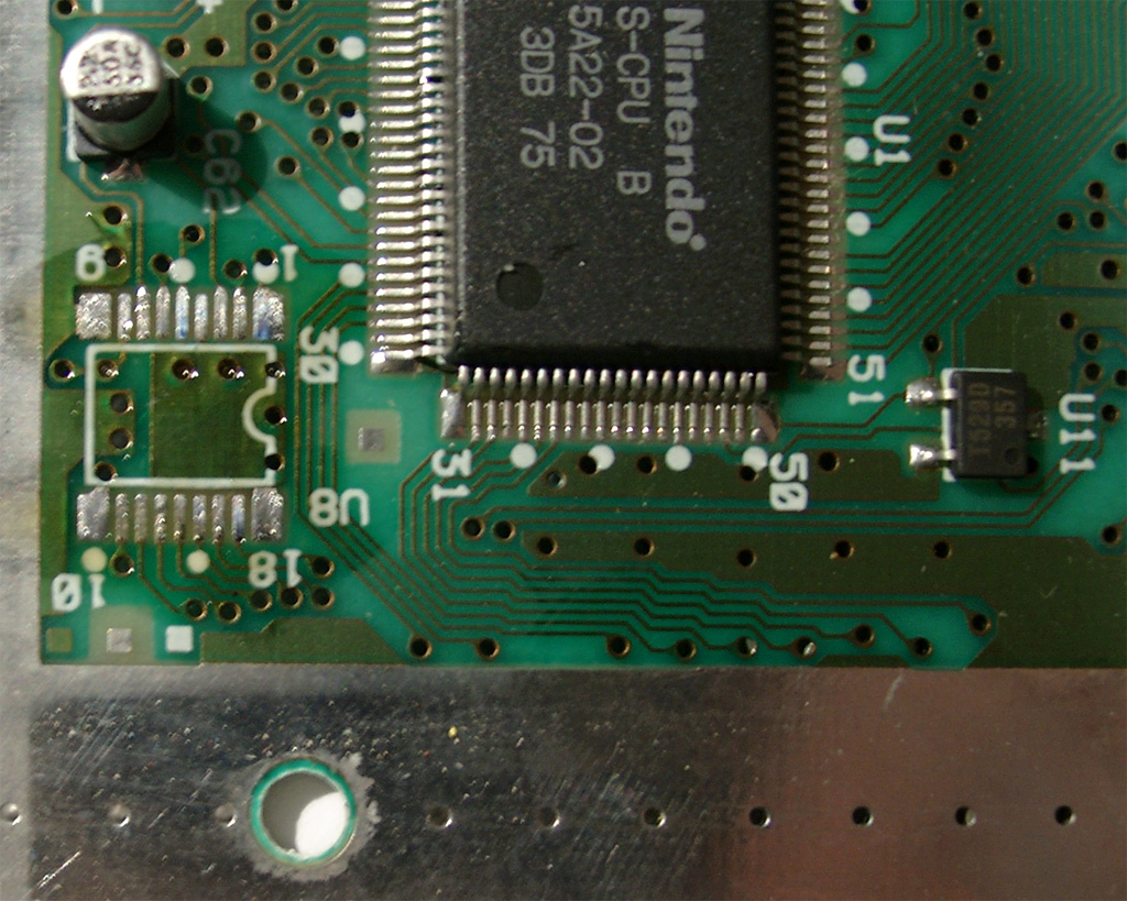
After removing the original CIC:
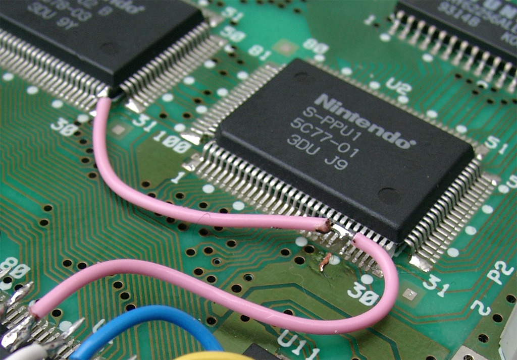
The usual 50/60Hz Pins:
You have to lift PPU2 Pin 30 and lift PPU1 Pin 24 and wire it together to Pin 12 @Pic12f630.
The Console is set to 60Hz if you set both Pins to GND
The Console is set to 50Hz if you set both Pins to 5V
2nd View:
Here you can see the wiring of the PIC:
More wiring:
You can set the PIC into 2 Modes
a) Pin 4 to 5V (I used this Mode, see the red wire)
b) Pin 4 to GND
And please set Pin 7 To GND, so the PIC is set to DUO-LED Mode (common cathode).
On the following picture the wire is missing!
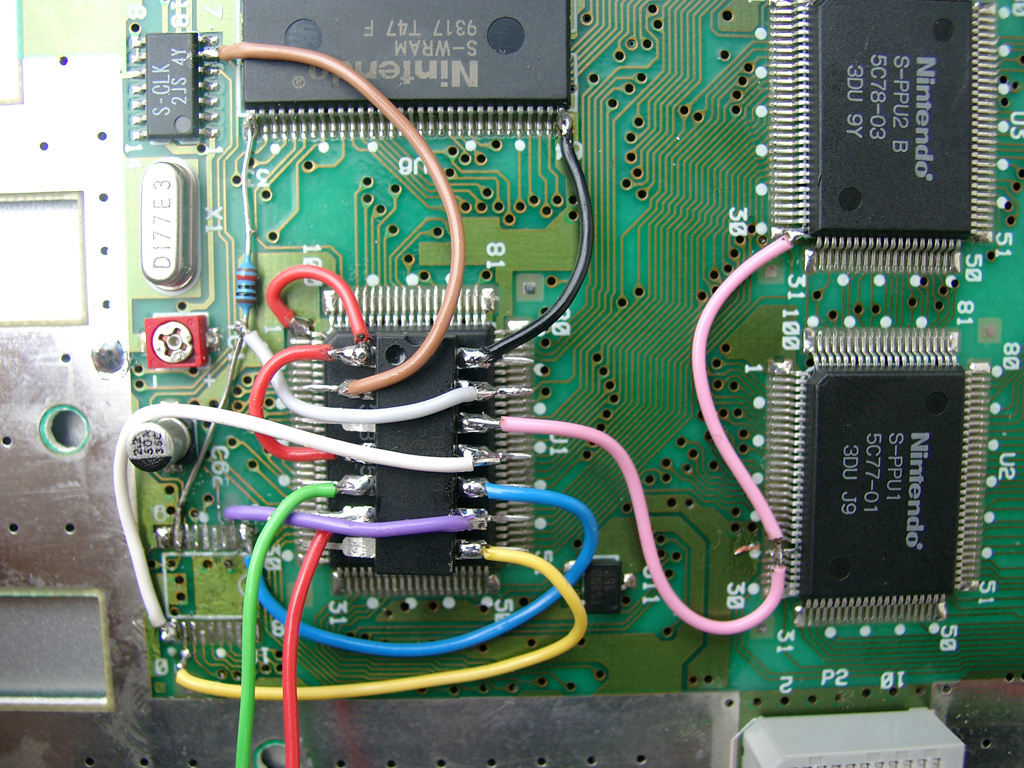
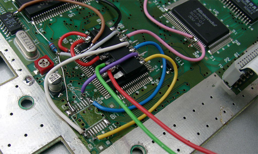
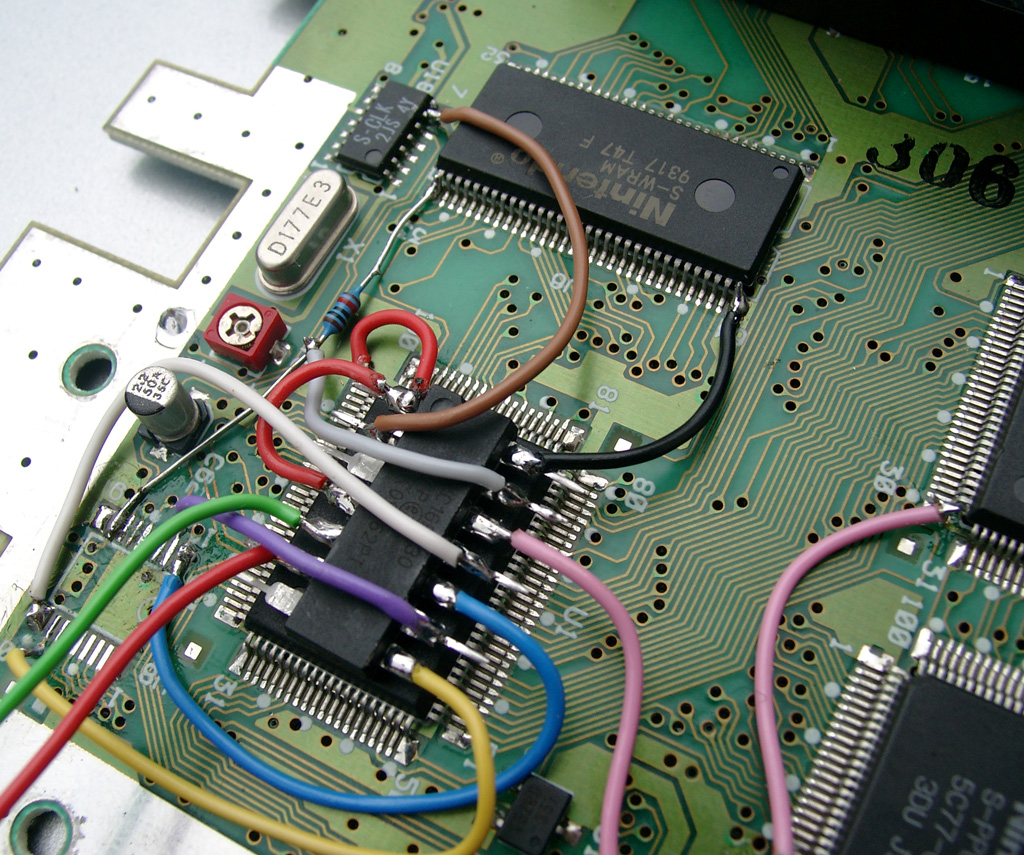
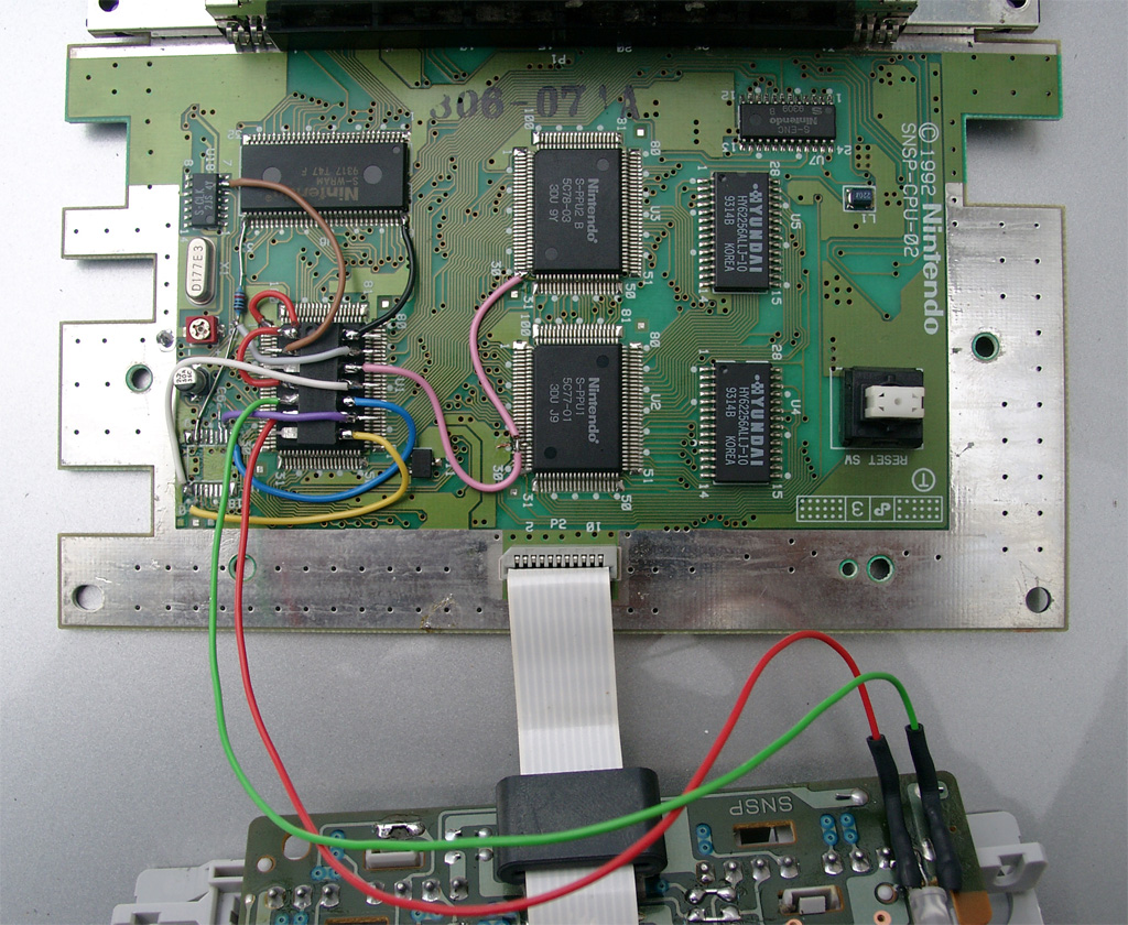
you can remove the original LED by heat both pins together and pull it a little bit out.
So you can cut the 2 pins of the original LED.
After this you can use a DUO-LED (gn/red) 5mm with 220Ohm Resistors. I solder the middle (GND) to the SNES Controllerport
To play import Controller or thinks like a superscope on a PAL-SNES you can shortcut all 4 Diodes on the controller port. (see picture2)
You can use two different LEDs:
a) a Duo-Led with common cathode (GND)
You have to set Pin 7 of the PIC16F630 to GND
b) a RGB-Led with common anode (plus)
You have to set Pin 7 of the PIC16F630 to 5V
Look here for a picture:
Some Info about the usage of the superCIC.
You can change between 50/60Hz and Auto Function by pressing the Reset Button for longer as around 0,5 sec. The current Status is shown by the DUO-LED. (red=60Hz, green 50Hz, orange=Auto).
After releasing the Reset Button the mode will be active. The SNES will not reset at this moment.
a) 50Hz Mode is active (green)
If you insert a PAL-Game, it will start with 50Hz
If you insert a NTSC-Game, it will start with 50Hz (if Pin 4 is set GND)
If you insert a NTSC-Game, it will start with 60Hz and switches to 50Hz after 9 sec. (if Pin 4 is set 5V)
If you insert a Game without CIC, it will start with 50Hz
b) 60Hz Mode is actice (red)
If you insert a NTSC-Game, it will start with 60Hz
If you insert a PAL-Game, it will start with 60Hz (if Pin 4 is set GND)
If you insert a PAL-Game, it will start with 50Hz and switches to 60Hz after 9 sec. (if Pin 4 is set 5V)
If you insert a Game without CIC, it will start with 60Hz
c) Auto Mode is actice (orange)
starting the Game in its native frequence.
If you insert a NTSC-Game, it will start with 60Hz
If you insert a PAL-Game, it will start with 50Hz
If you insert a Game without CIC, it will start with 60Hz
Here you can see a video, how the switching is working:
Here you can see a US-Unit with a RGB Led using blau and red part of the LED:
Posted in Nintendo, Switchless Mods | No Comments »
Saturn switchless Mod VA0 PAL Mainboard
Mittwoch, April 28th, 2010
today I done the switchless mod for a PAL Mainboard.
Its the third different mainboard i looked at.
Mainboard PC BD SATURN MAIN VA0 Pal

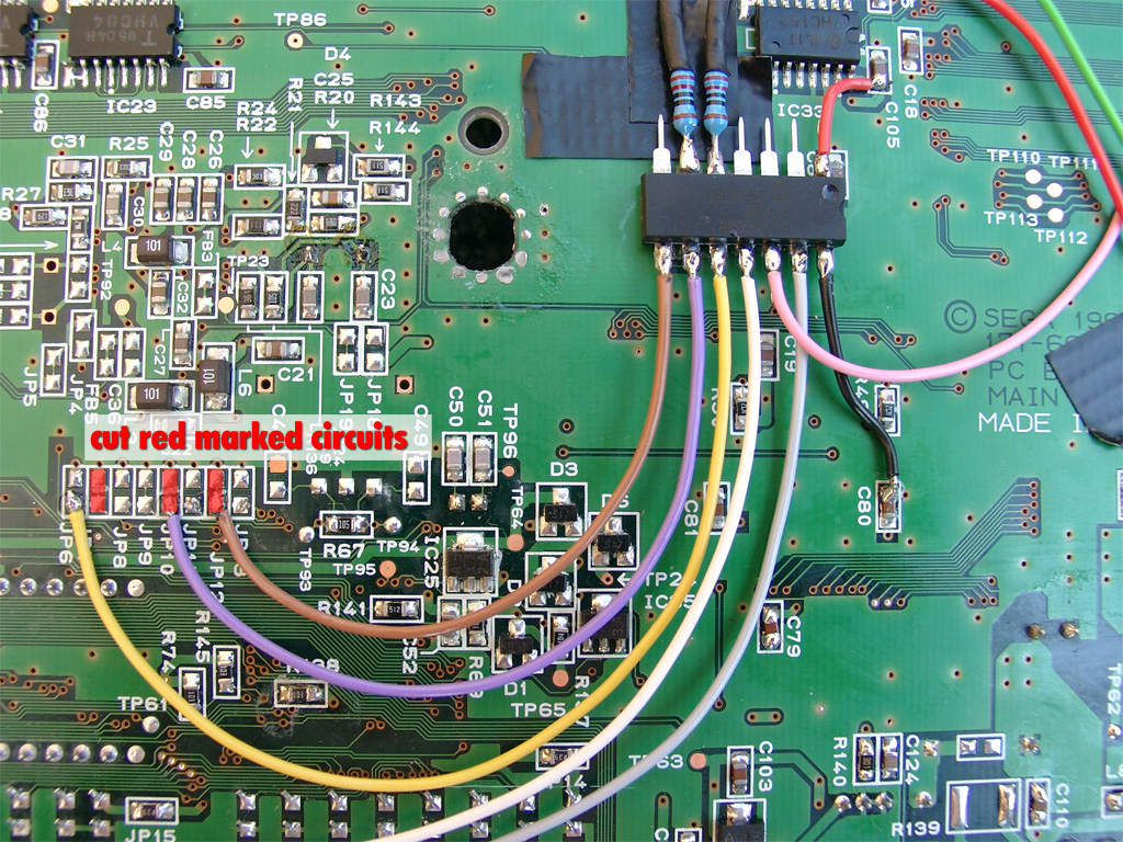
At the solder Side you will find some Jumper from JP 6 to JP 13
cut the three circuits at Jumper JP7,JP10,JP12 for Language preparation
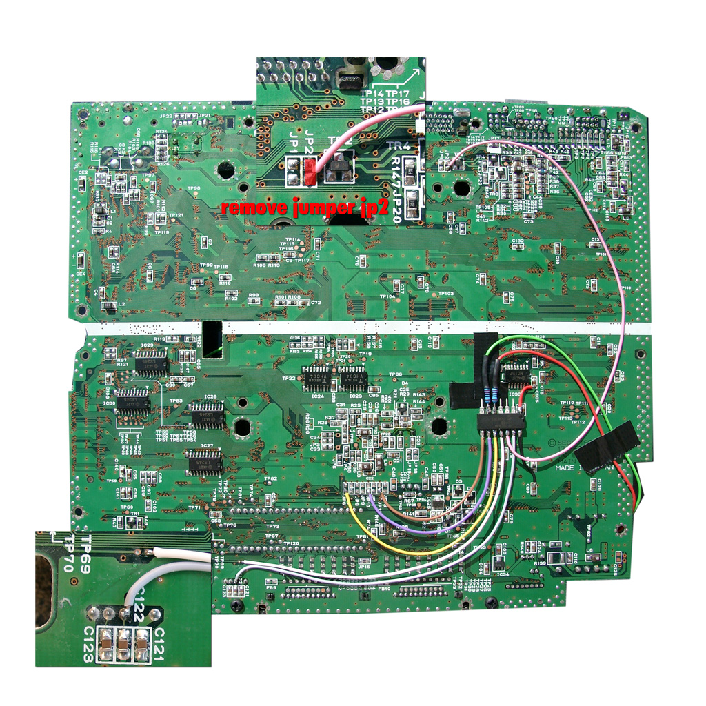
remove Jumper 2 (50Hz, 60Hz switching)
Wire PIC like shown at the picture:
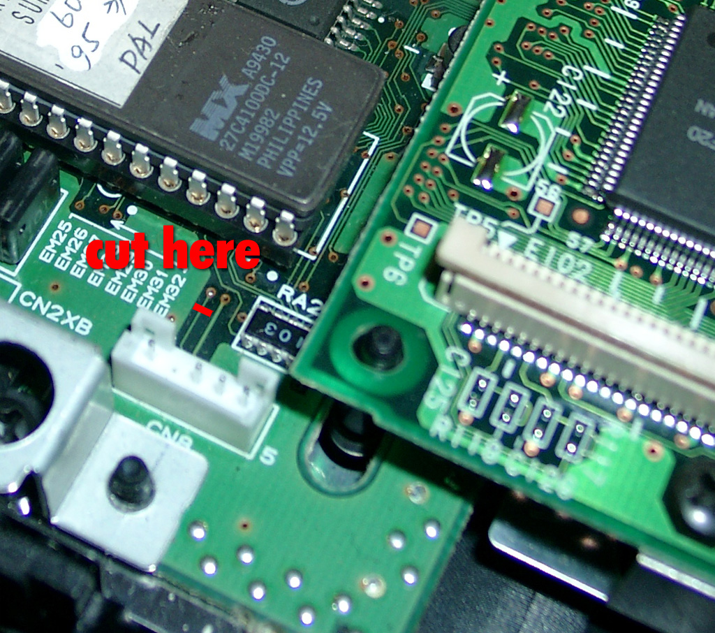
For make the Reset Button work, you have to cut this circuit on the parts site of the mainboard:
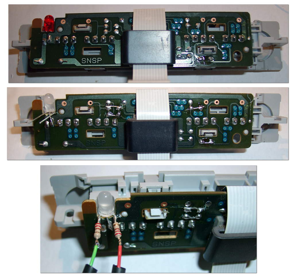
Remove the LED PCB. It holds a 5x2mm square LED.
Replace it by a Duo LED and use some glue
Left red wire, middle GROUND (take it from the mainboard), right green wire.

Posted in Sega, Switchless Mods | No Comments »
Sega Master System II switchless Mod
Dienstag, April 27th, 2010
Today I modded a Sega Master System II.
You can change between 50/60Hz via the „Pause“ Button.
The normal function of the pause is still working if you press it a very short time.
For working with sebs switchless mod, I done some modification on the code.
Here you can download the code: switchless MasterSystem Code
a) make use of common anode RGB-LEDs for brighter Leds
b) reduce the code to two modes 50 and 60Hz.
Here you can see the solder site of the SMS2 Unit. You have to cut the Pause Button Signal:
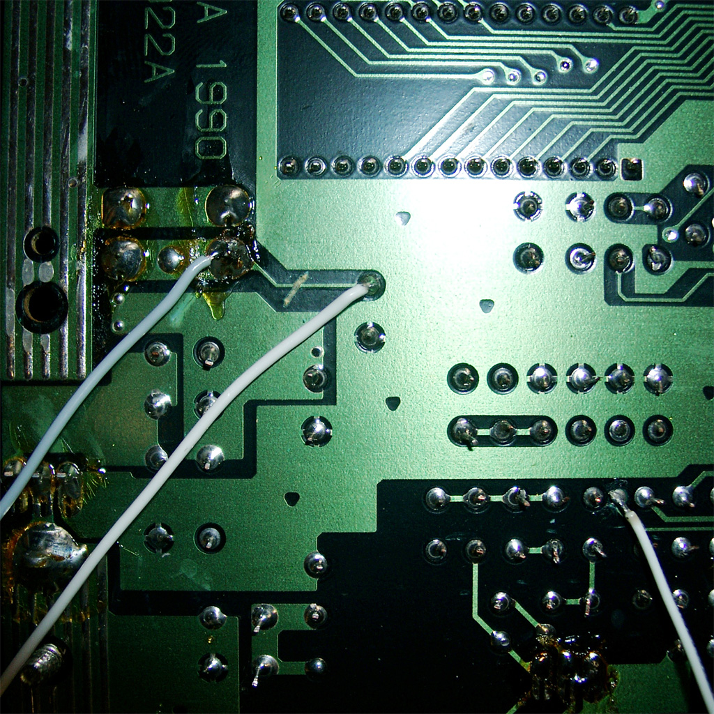
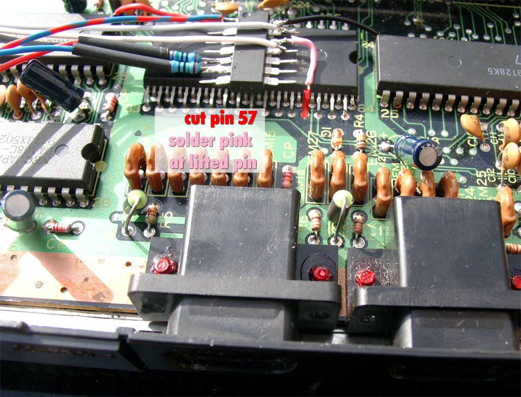
for making 50 and 60 Hz switching work you have to cut Pin 57 of
Sega IC 315-5246 (64 Pins):
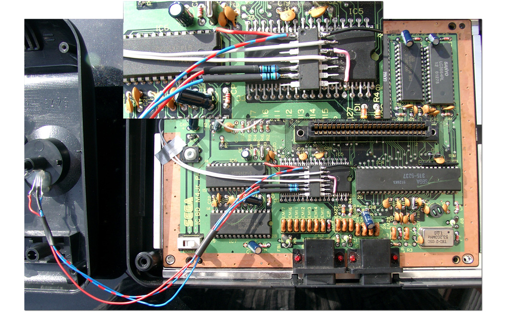
Here you can see the wiring of the PIC16F630
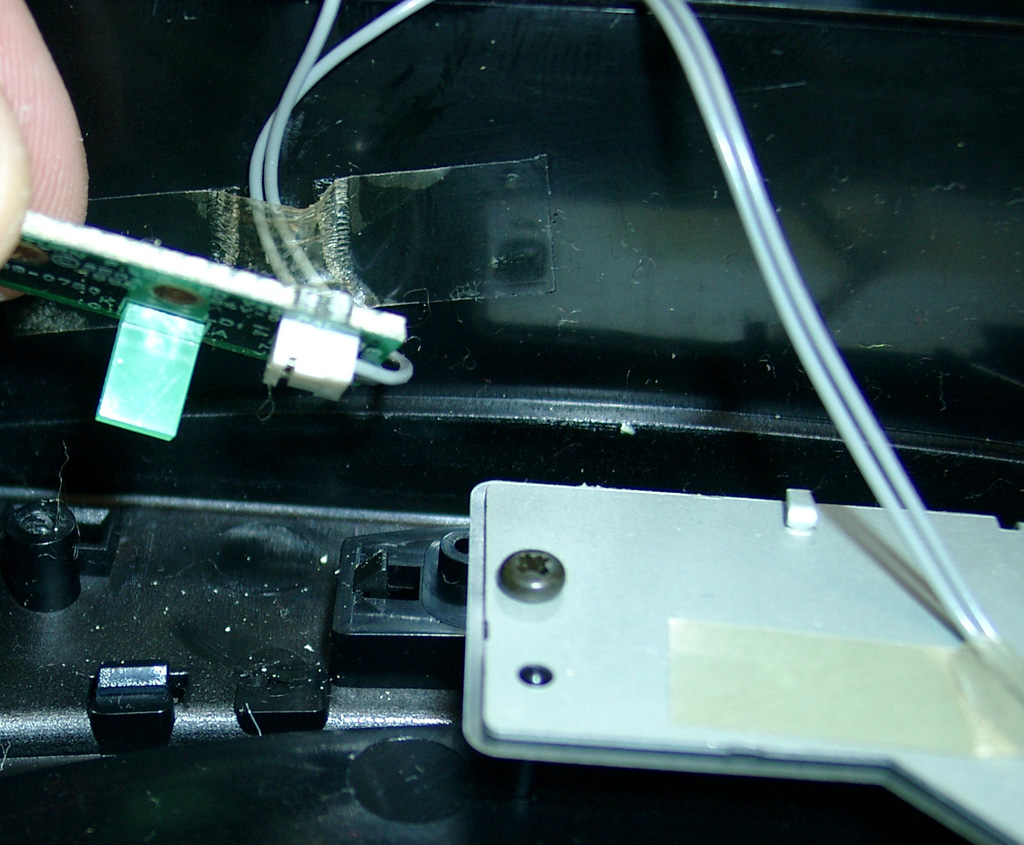
For Displaying the LED I put it under the Pause Button.
From the top its not so bright but it works:
english video
german Video
Posted in Sega, Switchless Mods | No Comments »
NeoGeo AES switchless MOD
Dienstag, April 20th, 2010
I am using a NEOGEO AES3-5 unit for the switchless mod today
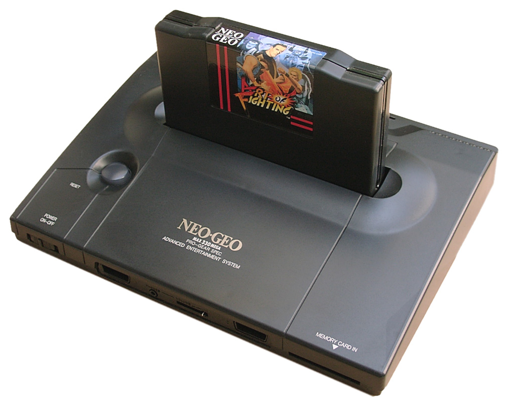
Rom Part: piggyback
I added a second Bios from Razoola the UNIBIOS. You can get it at www.wolfsoft.de or unibios.free.fr
Here you can find a good tutorial for piggyback the UNIBIOS http://www.mmmonkey.co.uk/
First you have cut pin 2 of the onboard Bio and lift the pin up:

use a DIP 40 socket to make a future replacement easier
Lift up pin 2 of the mainboard and pin 2 of the DIP-socket

The PIC 16F630 Part
As usually I am using the switchless mod from seb http://seb.riot.org/saturnmod/
And the inspiration from Pete Grimes Site: http://www.mmmonkey.co.uk/
This time I can’t use sebs pic code „out of the box“.
I have done some lite modifications to the code.
50/60Hz switching is inverted at the NeoGeo and NeoGeo can’t switch between 50/60 Hz during operation. So it is needed to do a reset after switching 50/60Hz.
The Country Mode must reduced from 3 to 2 and I have done some slight changes for make a RGB-LED working. The difference at the RGB-LED it is wired common Anode
You will find the source code here.
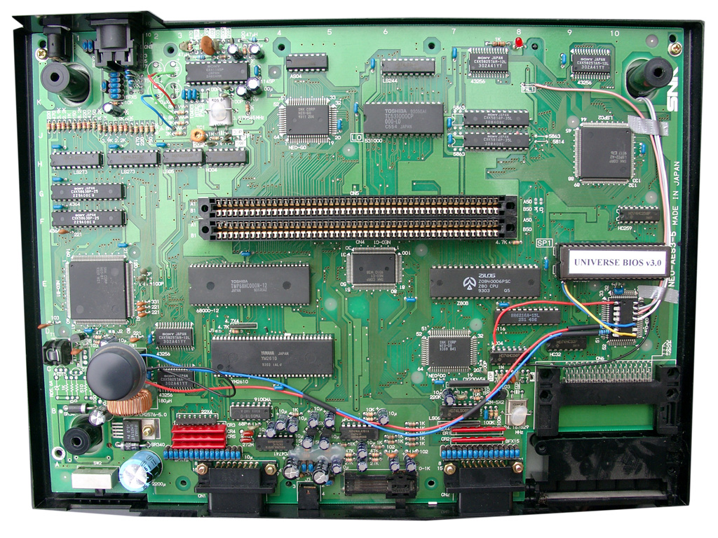
PIC 16F630 Wiring
red wire PIC Pin 1 (5V) taken from IC HC04 Pin 14
black wire PIC Pin 14 (GND) taken from IC HC04 Pin 7
red wire PIC Pin 5 to RGB-LED (Resistor 150Ohm)
blue wire PIC Pin 6 to RGB-LED (Resistor 150Ohm)
yellow wire PIC Pin 8 to lifted Pin 2 of the DIP-socket
blue wire PIC Pin 10 to lifted Pin 2 of the onboard Bios
white wire PIC Pin 11 to solder site of mainboard (Reset Signal)
pink wire PIC Pin 12 to PAL Jumper right site (LSPC2-A2 TSOP Pin 64)
grey wire PIC Pin 13 to solder site of mainboard (Reset Button)
remove the pal jumper, solder pink to the right site of the jumper
(left site of PAL1 5V, right site to LSPC2-A2 TSOP Pin 64 for 50/60Hz definition)
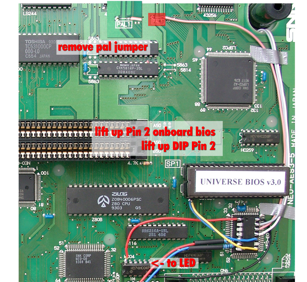
Here you can see the lifted pins
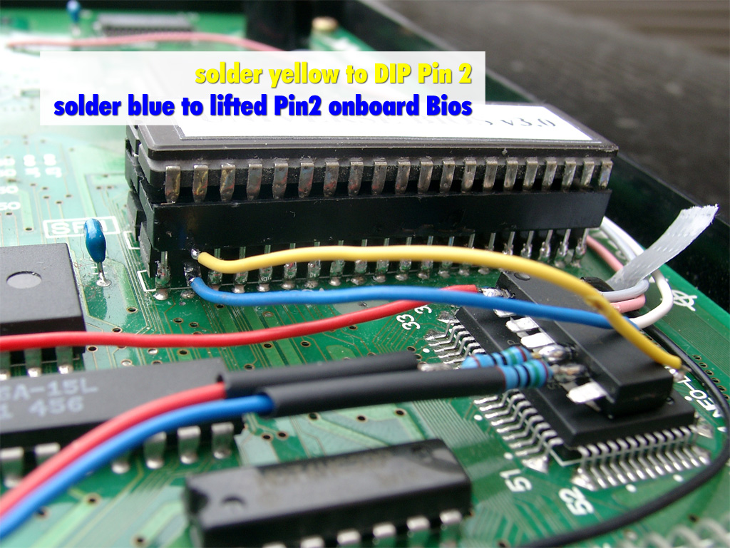
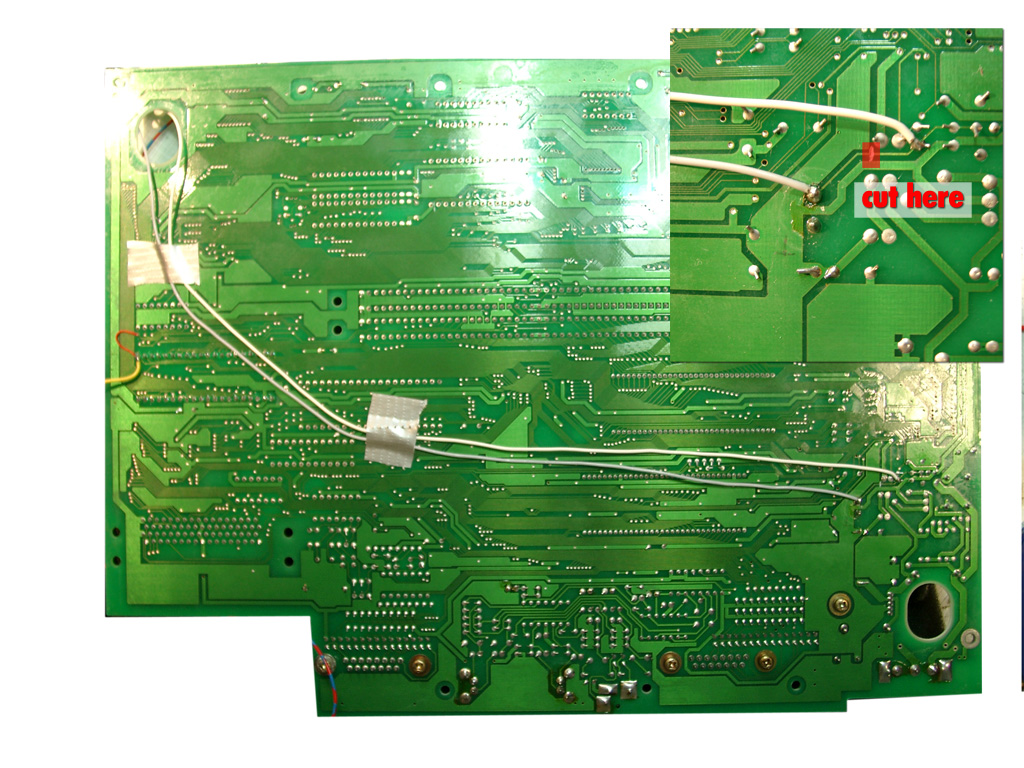
on the solder site you have to cut one circuit (see red marked area) and solder grey and white
(to split the original Reset Button Signal and make use of the Reset Button via the PIC)
complete mainboard top site
The black wire at the RGB-Led under the Reset Buttons is carrying 5V and taken from a nearby IC
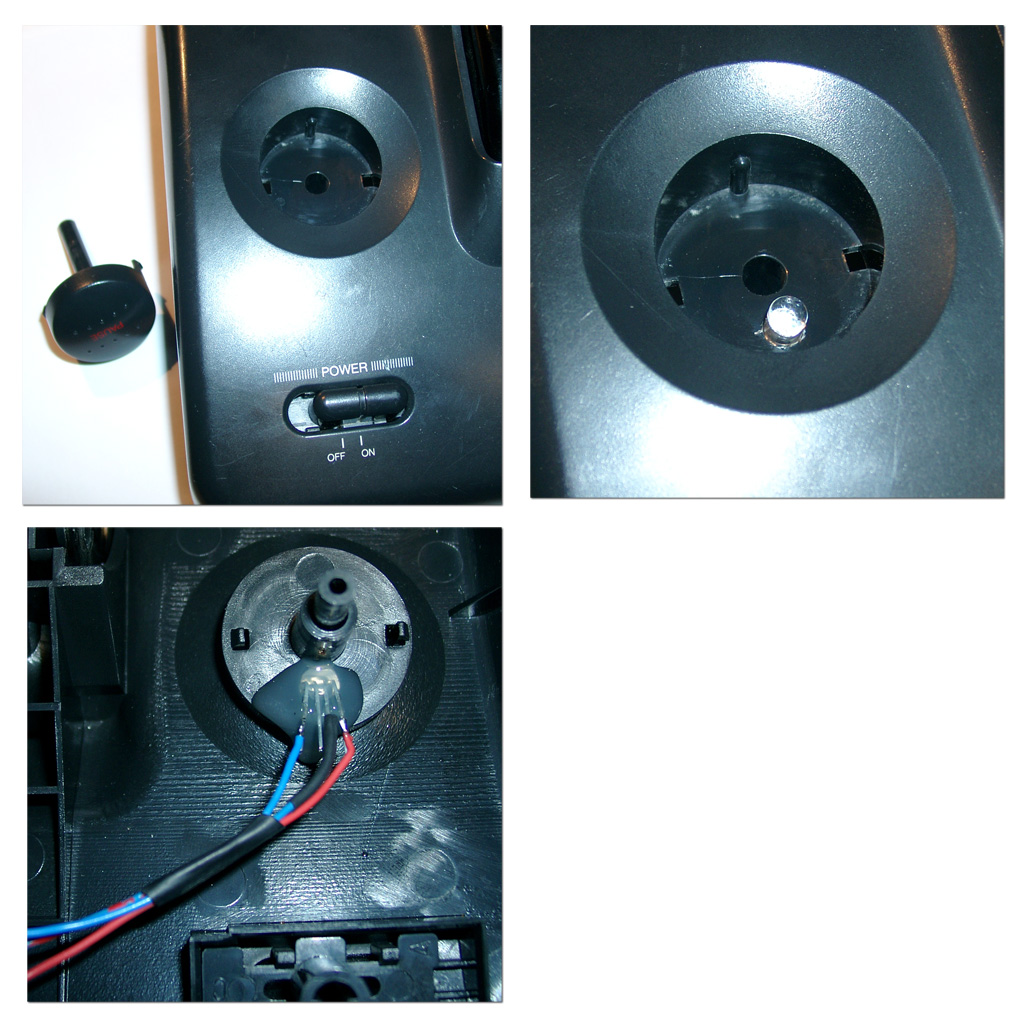
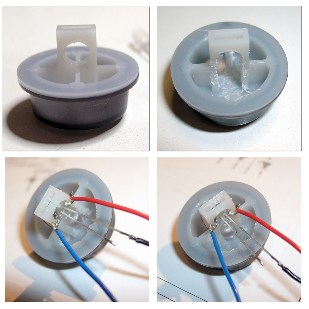
Now you have to add the RGB Led to the power switch, with help of a dremel.
I done it the same way as pete from www.mmmonkey.co.uk
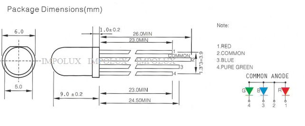
For more power I am using now a RGB-Led with black wire common Anode 5V
english video
german Video
Posted in NeoGeo, Switchless Mods | No Comments »
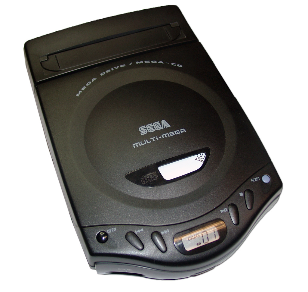
Worldwide First Sega CD-X, REAL multi-mega switchless mod
Freitag, April 16th, 2010
This mod has been a long time in my head and I am happy to make it become real now 
The Sega CD-X is a little great unit, you can take with you as a CD-Walkman and it includes a complete Sega Genesis and a Sega CD in one unit.
After done the previous modding of Genesis 2 in combination with Sega CD 2 and 32X I done the same for this little beauty.
We can offer you the complete modding, at our website: www.wolfsoft.de
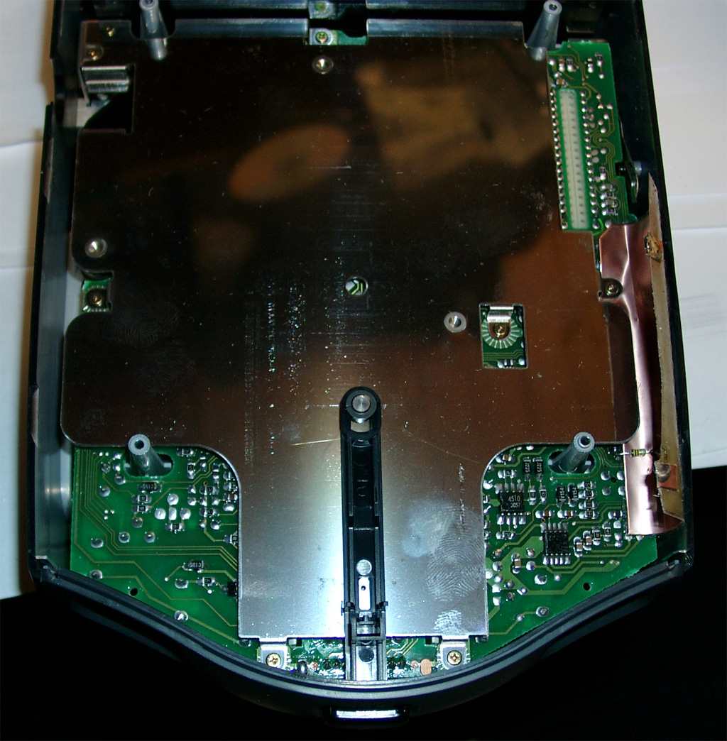
The shielding carries GND for the Mainboard. It will not work without it. For testing you can use a wire like the following pictures:

The battery have to be replaced its a solder Version of ML 2016 (3V) Li-AL Rechargeable Batterie.
Modell: ML2016-LF (Maxell)
http://datasheet.octopart.com/ML-2016-T25-Maxell-datasheet-558430.pdf

After removing the shielding you can find the jumper for 50/60Hz and the Country Settings
The default for a europe unit JP3 is set and JP2. You will have to remove any jumper you will find
at JP1, JP2, JP3, JP4.
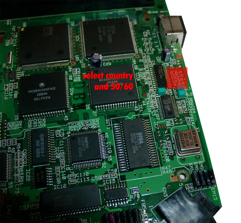
Some more Info about the Jumper Area:
The circuits are going straight to the big SEGA 315-5660 IC
Pin 46 at Sega 315-5560 -> 50/60Hz switching. GND= 50Hz and 5V = 60Hz (JP3, JP4)
Pin 107 at Sega 315-5560 -> Country settings. GND= jap. and 5V = engl. (JP1, JP2)
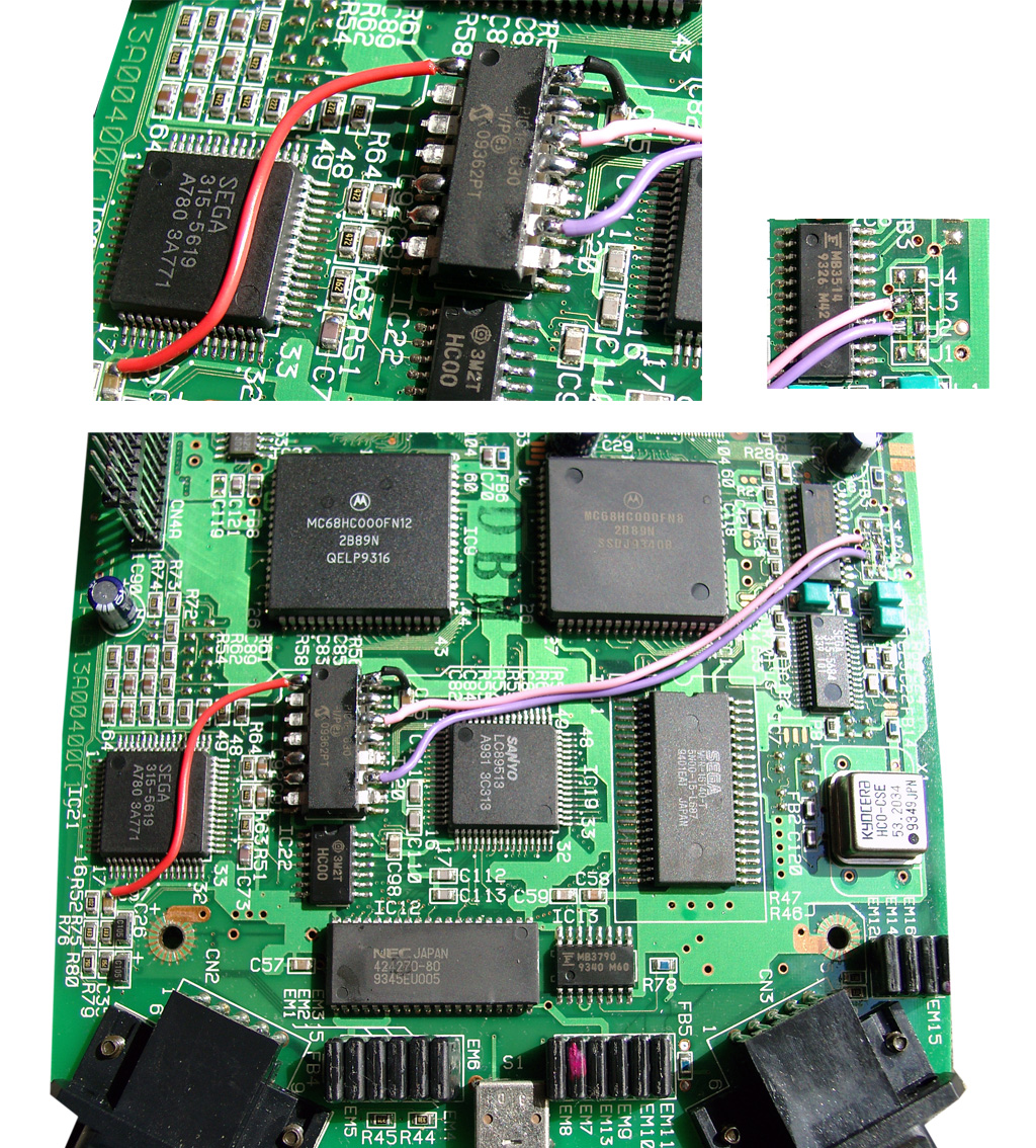
Now its time to make use of a PIC 16F630 with sebs Code.
red wire 5V, black wire GND, pink wire 50/60Hz, purple wire country setting
Now we have to take the 2nd Mainboard (CD-Area). We have to mod the Display with two Duo Leds. First you have to remove the shielding.
Desolder the Display Unit.
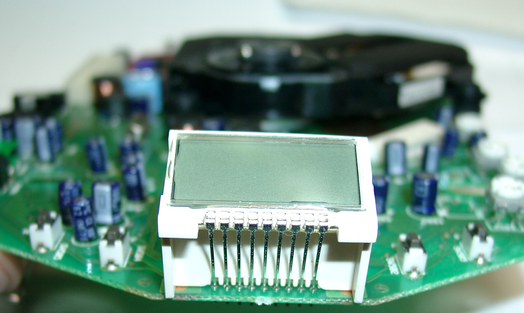
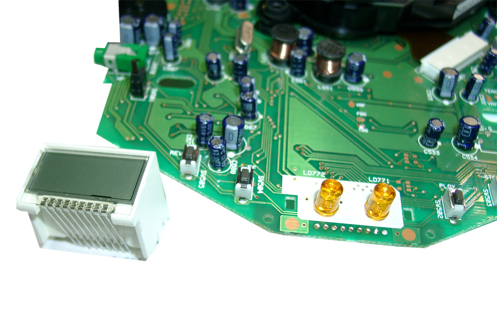
- Remove the two original LEDs.
- Use some tape and double sided adhesive tape
- The Center of the 3 pins of the DUO-LED is GND. Solder both to the GND Area of the mainbord
(I used some fiberglas pencil) - make space for the legs of the LED at the PVC of the Disyplay
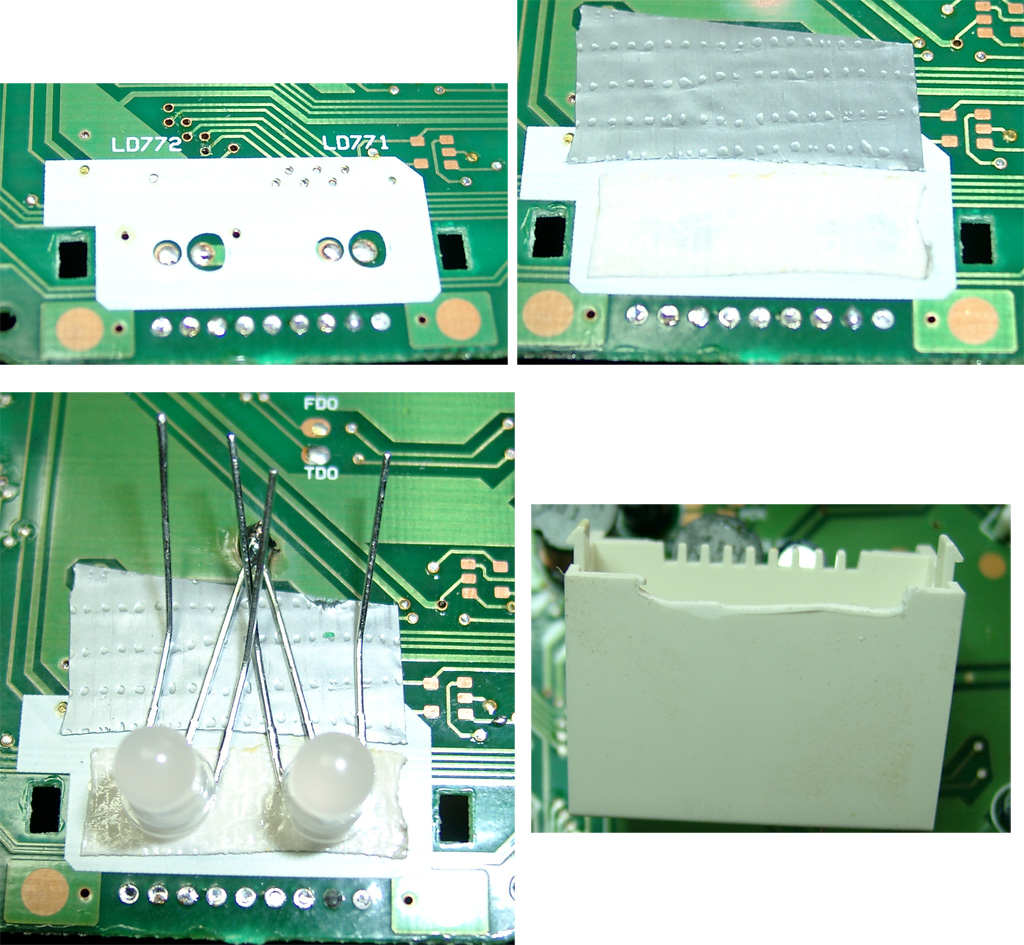
use four 220Ohm resistors and head shrink tube to avoide short curcuit.
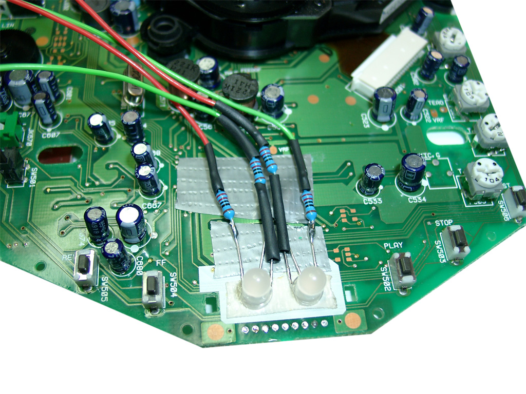
Here you can see the routing of the 4 wires bounded with some tape.
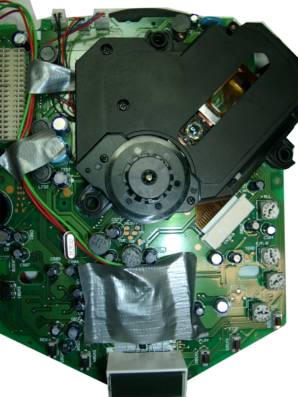
Now it is time to get the „power“ over the reset button. It is placed on the CD-Mainboard. Lucky the Signal is going through the 36 Pin Connector on the left site.
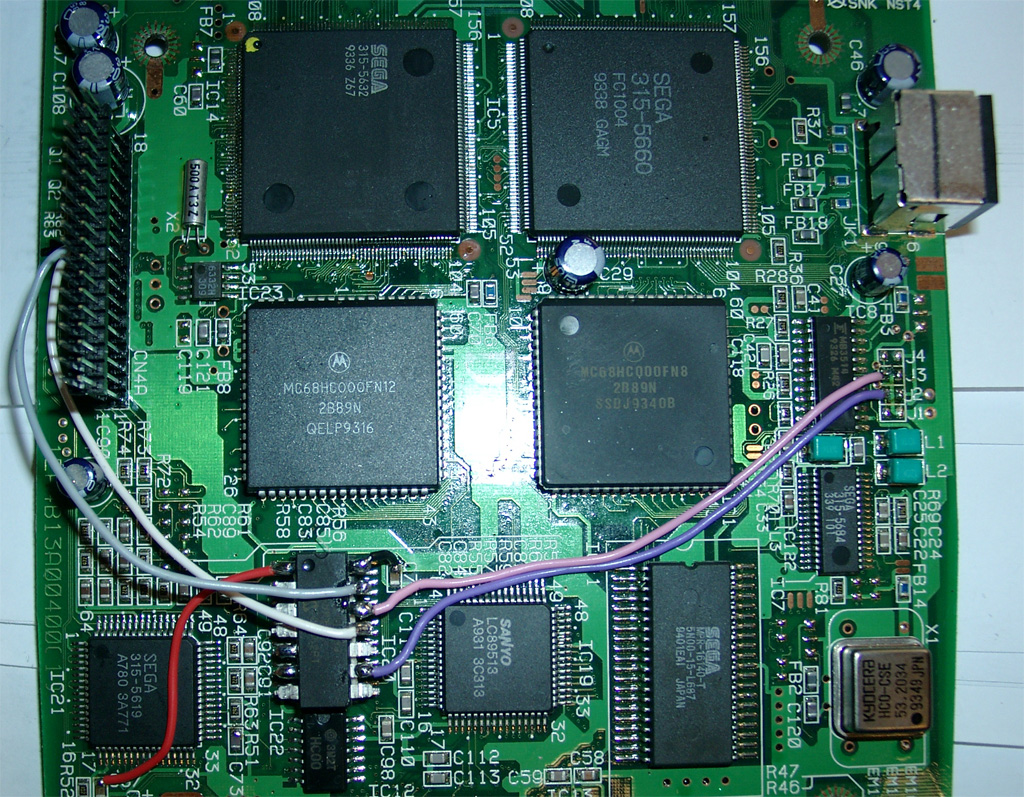
You will have to cut pin 11 at the outersite of the connector.
PIC Pin 13 grey is connected to the upper site. Its for the Reset switch
PIC Pin 11 white is connected to the lower site (Reset Sega 315-5660 IC Pin 78)

Rom Part – for playing Cds around the world
You are in need of a Eprom (27c2004) and burn all 3 bios Version into it. The usa, japanese and pal Version. You can select the different Bios Version via A16 (Pin 38) and A17 (Pin 39) of the Eprom.
The order is: USA-> JPN -> EUR.
You can do it by yourself. Take the CD-Bios Versions and make a byteswap each of them.
The concat the 3 Files via Windows Commandline copy
copy /B usa.bin + pal.bin + jpn.bin switchless.bin
The final goal is to get 2 wires from the 16F630 PIC to the Eprom.
Here we make use of 2 wires from the Sega Expansionport.
|
PIC 8 /Eprom 38 |
PIC 10 /Eprom 39 |
|
|
EUR |
0 |
1 |
|
JPN |
1 |
0 |
|
USA |
0 |
0 |
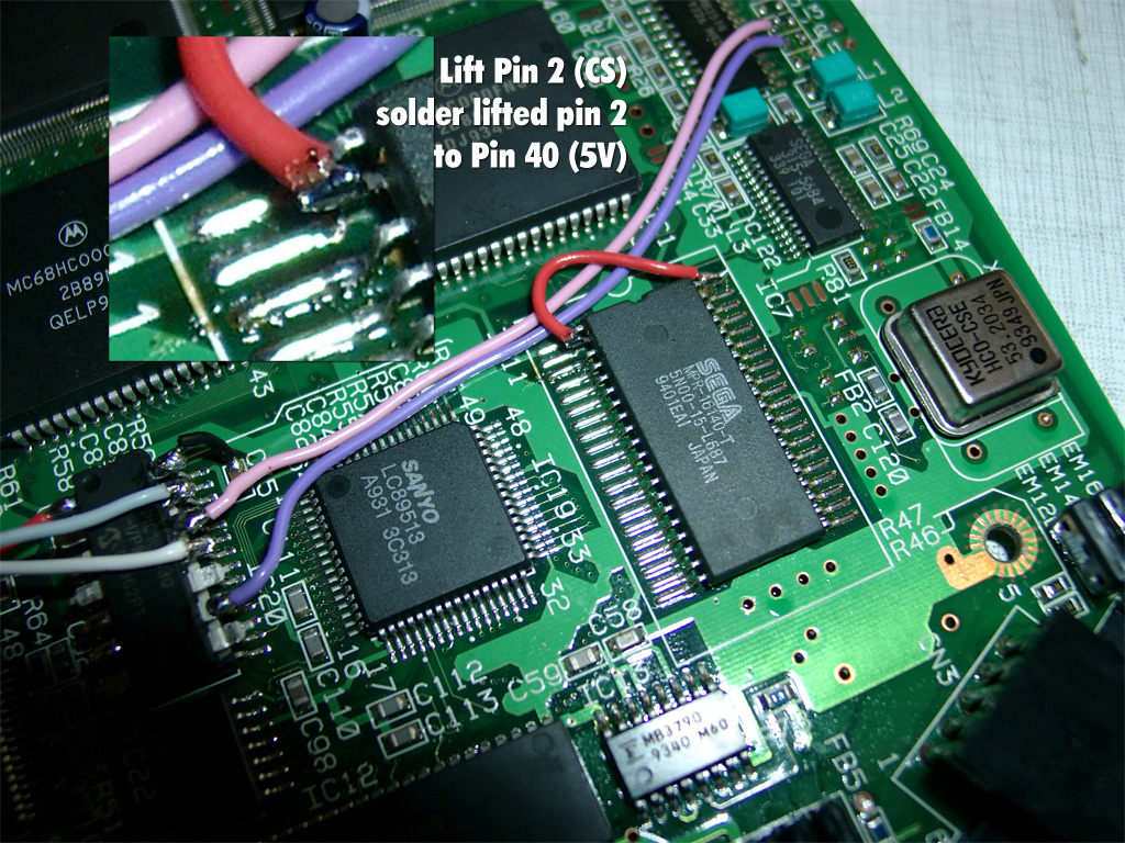
First you have to disable to onboard bios. Desolder PIN 2 (CS) of the onboard ROM and lift the pin up. Solder a red wire from the lifted Pin 2 of the ROM to Pin 40 (5V) of the ROM.
Now its time to prepare 38 wires each 5-6 cm and do some soldering
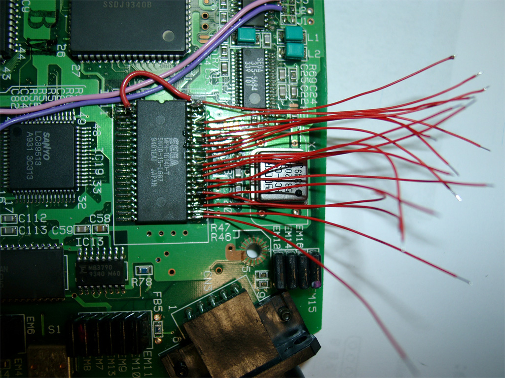
Wire blue and yellow as you see on the picture. This to wires will do the Bios selection:
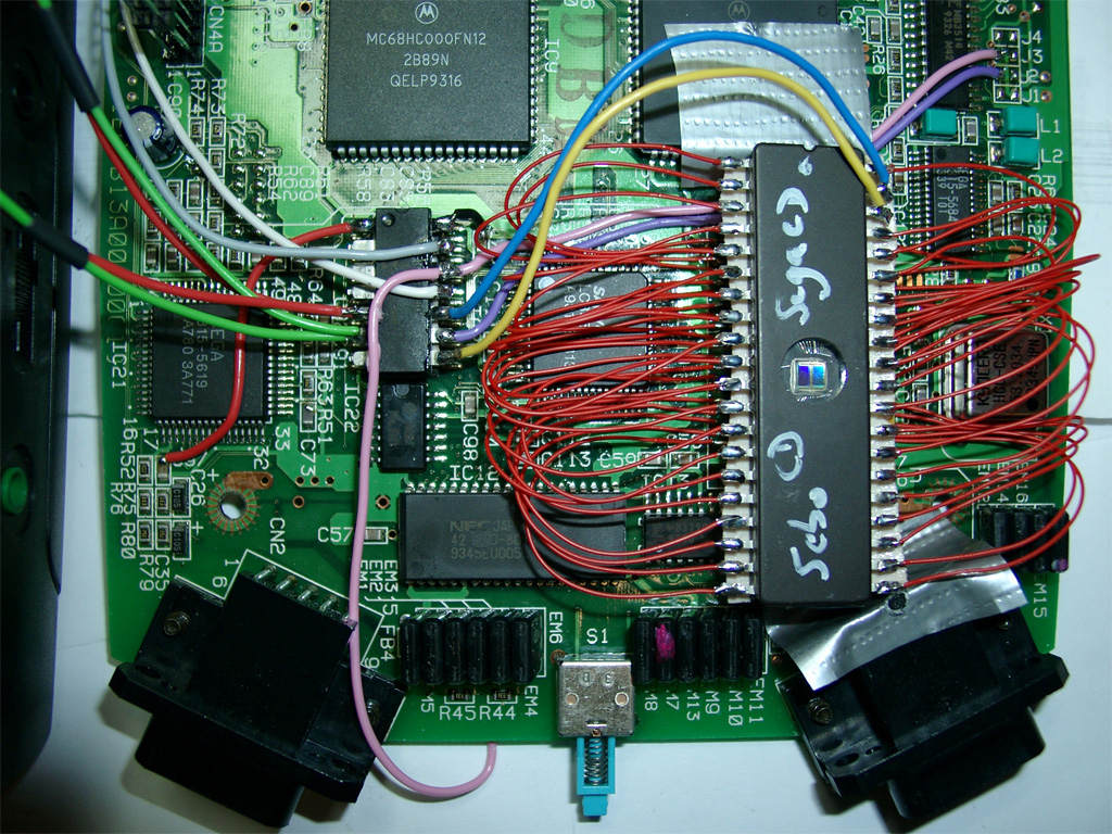
red and green coming from the 5mm Duo-Leds. Solder both parallel to PIN 5,6 of the PIC
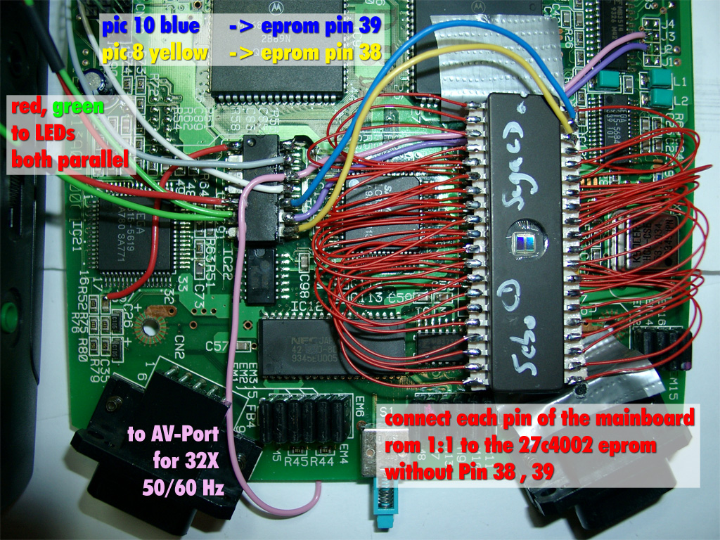
Adding Sega 32X Support (optional)
The pink wire to the AV-Port is optional, only necassary for 32X support
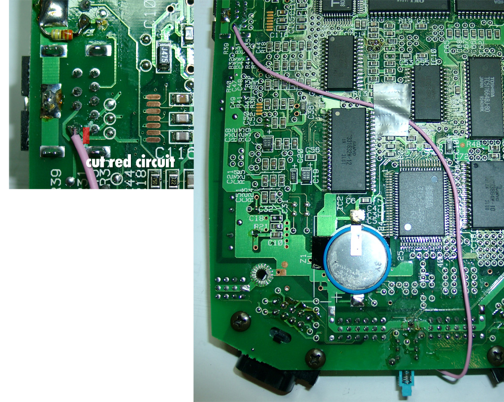
You will have to cut the red marked circuit and solder a pink wire to Pin 6 of the AV Port
We will disable the Mono-Audio for this function. This will not be a problem, because STEREO-Audio is still working. (Who needs mono ?)
On the right picture you can see the right routing for the wire:
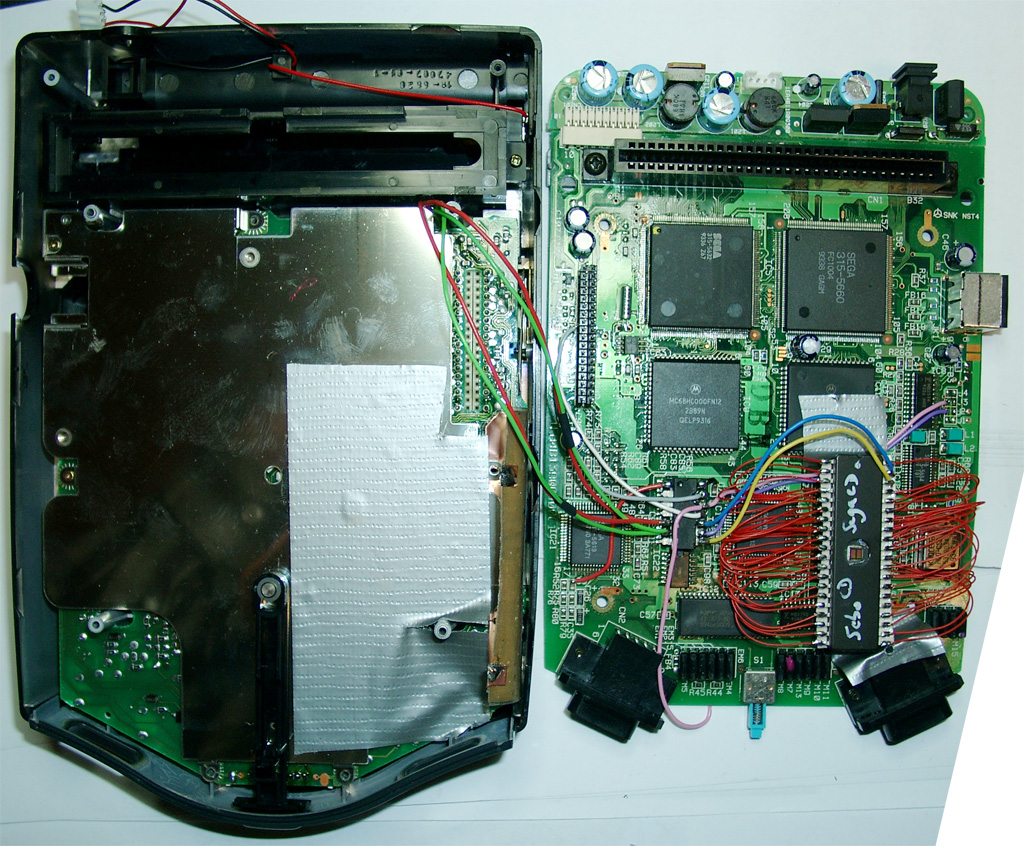
To prevent short circuits use tape on the left site of the CD-X.
Here you can see the routing of the LED wires.
Make sure no red/green wire is nearby or inbetween of the 36 PIN connector between the two mainboards:
german:
you can see the different colors:
Posted in Sega, Switchless Mods | No Comments »
Sega Genesis 2 ultimative switchless mod
Donnerstag, April 8th, 2010
Inspired from petes fabulous site www.mmmonkey.co.uk and his switchless mods,
I want to make the ultimative Sega Genesis 2 switchless MOD including 32X and Sega CD2.
In the beginning we have to mod the Genesis 2 with the switchless mod, like I done before.
(Thanks to SEB for the great PIC Code).
Difference between standard Sega Genesis switchless mod
For making a 32X working you are in need of the pink wire. This signal is needed in the 32X.
We can make use of the A/V connector cable between the Genesis 2 and the 32X. The Mono Audio Signal is not in use, so we can cut the original Mono signal at the Genesis 2 A/V connector and the 32X A/V connector.
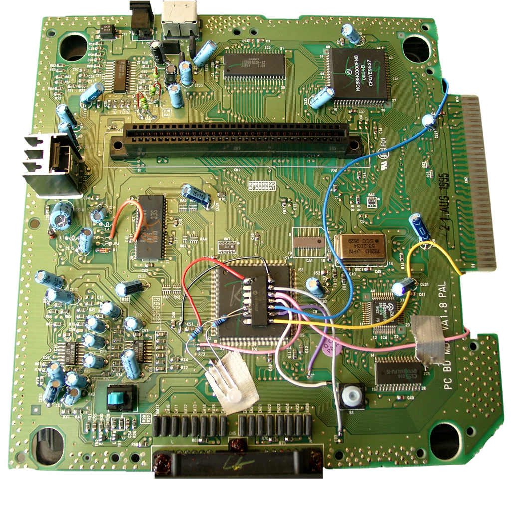
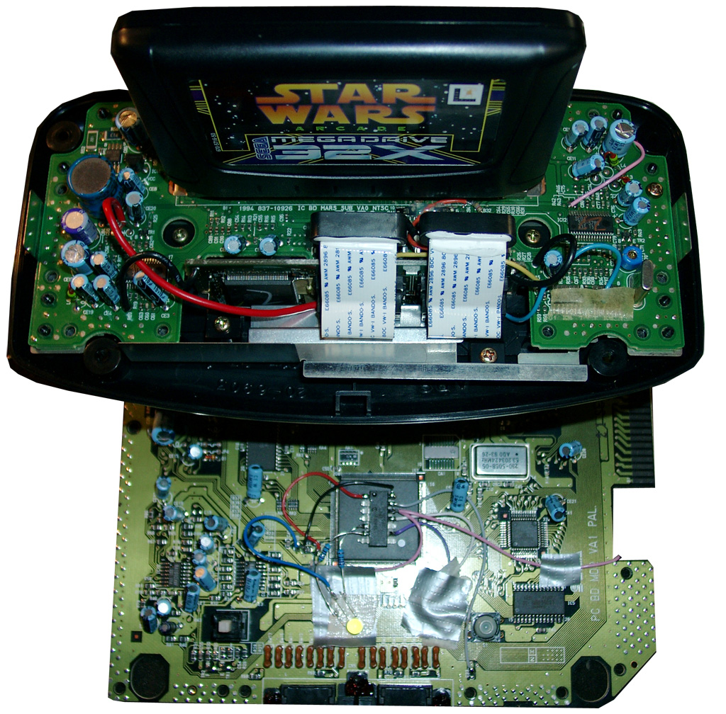
Here you will see the Sega Genesis 2 switchlees mod including the 3 more wires (yellow, blue, and pink).
The Pink is needed for the 32x.
Blue and yellow is needed if you want to make a Sega CD working too.
For 32X support add a 2nd pink wire to Pin 12 of the PIC.
At the solder site you have to cut the cirquit path to Pin 6 of the A/V Port and solder the pink wire to Pin 6 of the A/V Port.
For Sega CD support you have to cut Pin A01 (yellow wire) and Pin A30 (blue wire) of the Genesis Expansionsport and solder the 2 wires to the PIC Pin 10 blue and PIC Pin 8 yellow.
Backsite of the Genesis 2:
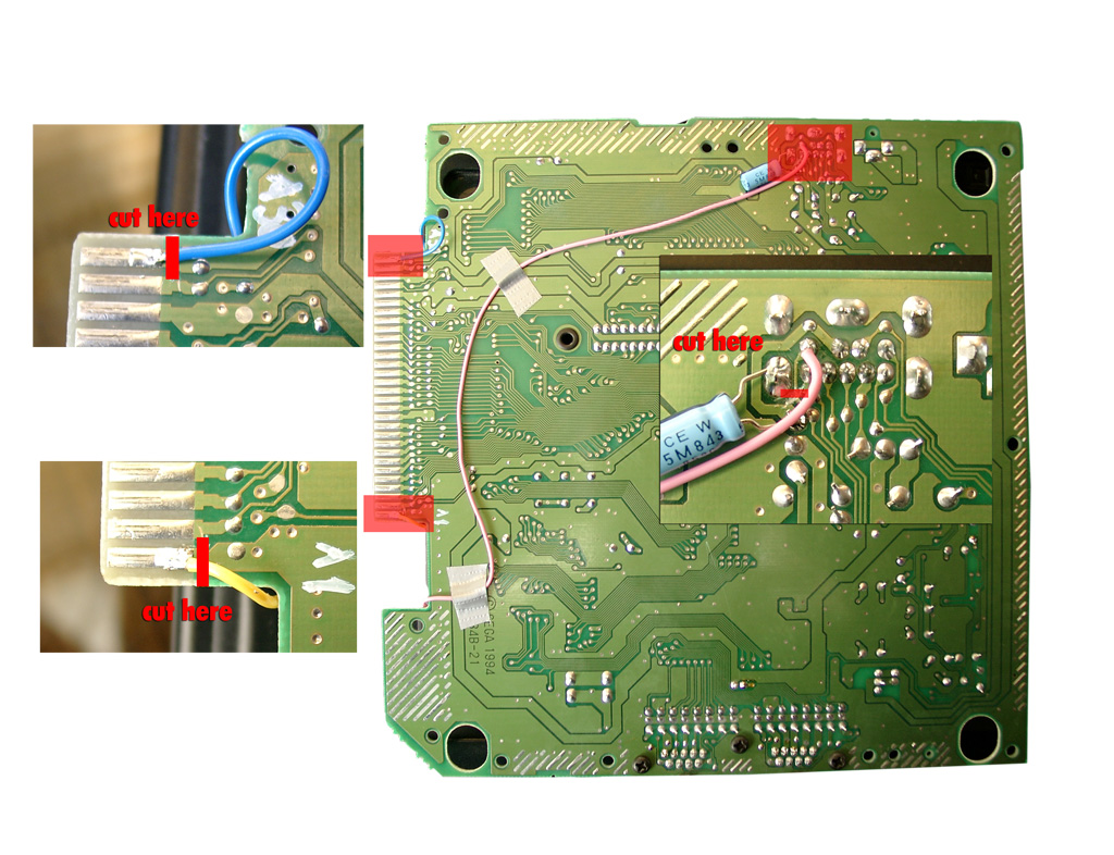
Adding 32X support
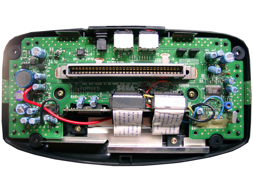
First you have to open the 32X and remove the shielding.
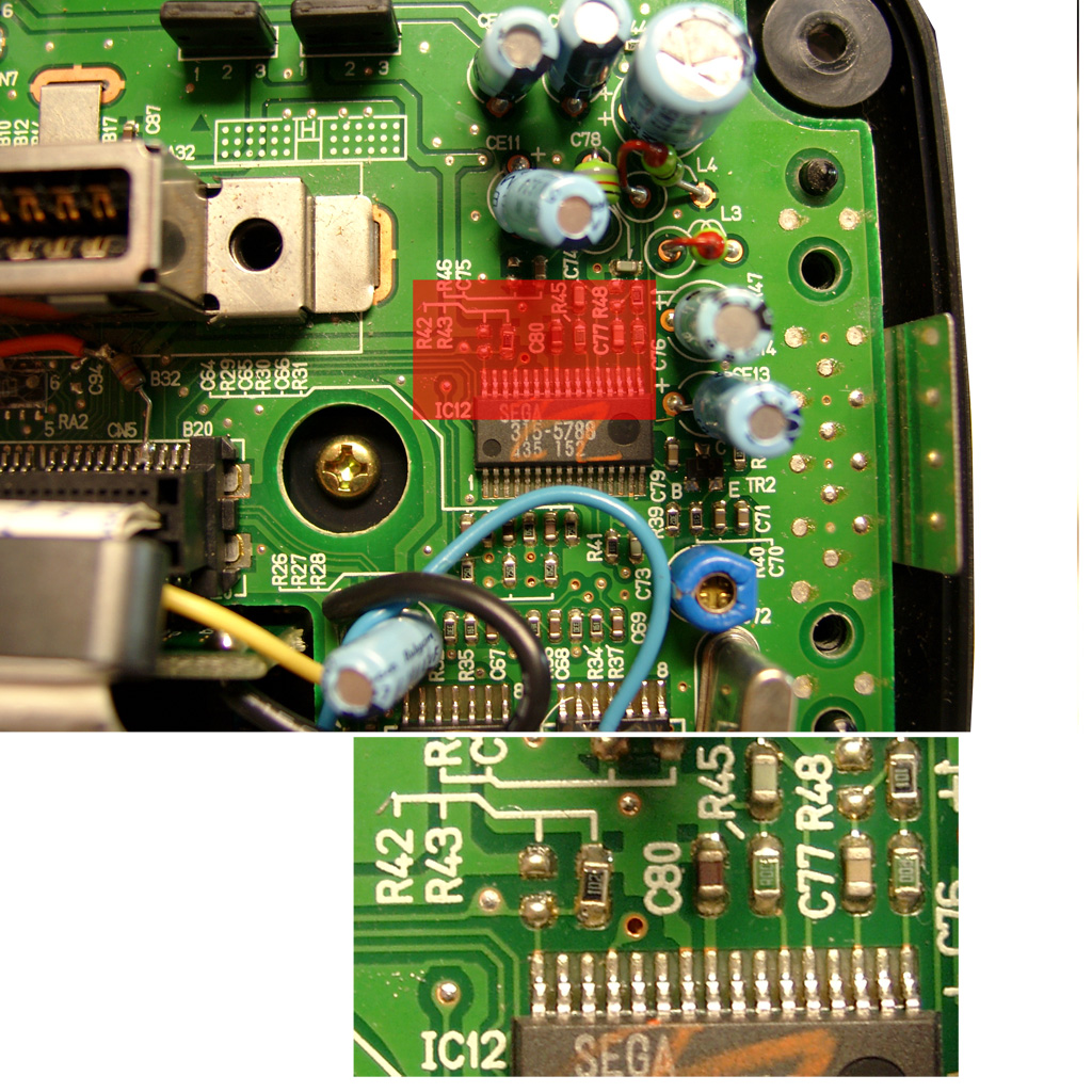
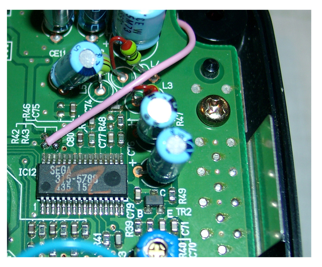
The only protection of the 32X is the 50/60Hz settings. You will find it at the right site of the mainboard IC12 SEGA 315-5788.
You will find R43, if its a PAL 32X (Pin 32 to GND) -> 50Hz
You will find R42, if its a NTSC 32X (Pin 32 to 5V) -> 60Hz
Remove the Resistor
Sega Genesis 2 A/V Pinout
|
Pin |
Description |
|
1 |
Blue |
|
2 |
+5V DC |
|
3 |
Green |
|
4 |
Composite Video |
|
5 |
Sync |
|
6 |
Audio Mono |
|
7 |
Red |
|
8 |
Audio Stereo L |
|
9 |
Audio Stereo R |

On the solder site you will have to Cut the cirquit path to Pin 6 of the A/V Port.
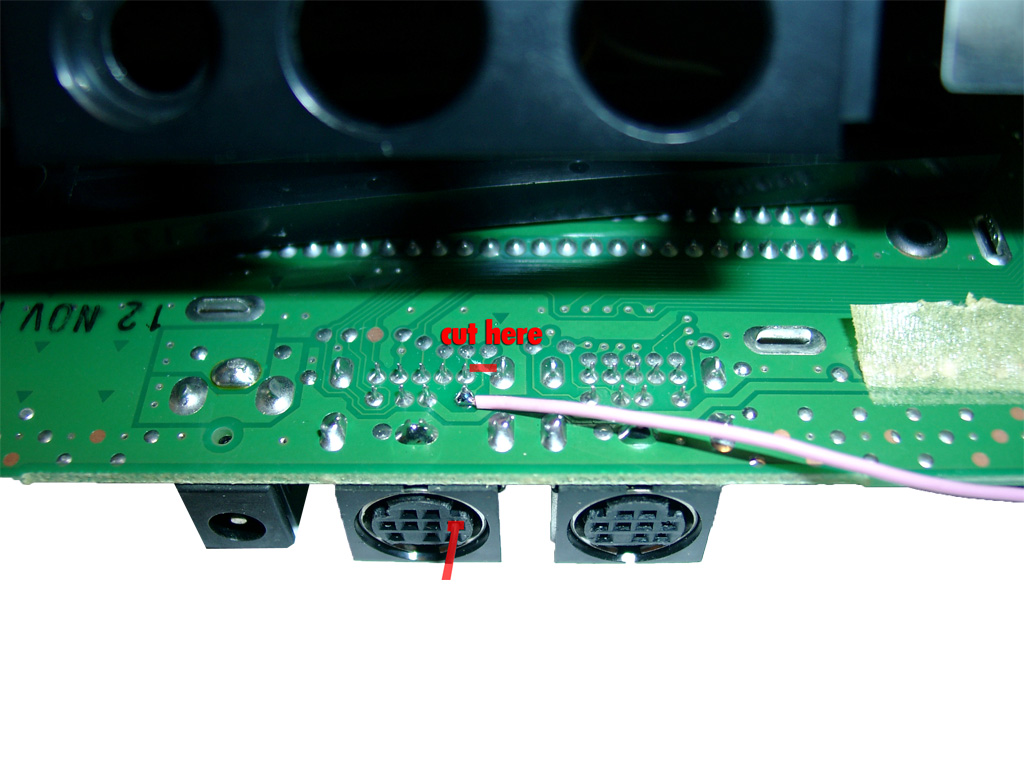
Solder one pink wire from AV Out Pin 6 (solder Site) to Pin 32 of IC12 (component site)
Adding Sega CD 2 support
You are in need of a Eprom (27c2004) and burn all 3 bios Version into it. The usa, japanese and pal Version. You can select the different Bios Version via A16 (Pin 38) and A17 (Pin 39) of the Eprom.
The order is: USA-> JPN -> EUR.
You can do it by yourself. Take the CD-Bios Versions and make a byteswap each of them.
The concat the 3 Files via Windows Commandline copy
copy /B usa.bin + pal.bin + jpn.bin switchless.bin
The final goal is to get 2 wires from the 16F630 PIC to the Eprom.
Here we make use of 2 wires from the Sega Expansionport.
Pin8 yellow 16F630->Exp Port Pin A01@Genesis 2->Exp. Port Pin A30@SegaCD2->Pin 38Eprom
Pin 10 blue 16F630->Exp Port Pin A30@Genesis 2->Exp. Port Pin A30@SegaCD2->Pin 39Eprom
Pin A01 and A30 of the Expansionsport carrying GND. There are many ground Signals at the Expansionsport. So we can cut these two of and make use of the free Pins for the Bios select.
|
PIC 8 /Eprom 38 |
PIC 10 /Eprom 39 |
|
|
EUR |
0 |
1 |
|
JPN |
1 |
0 |
|
USA |
0 |
0 |
First you have to remove the original Bios:
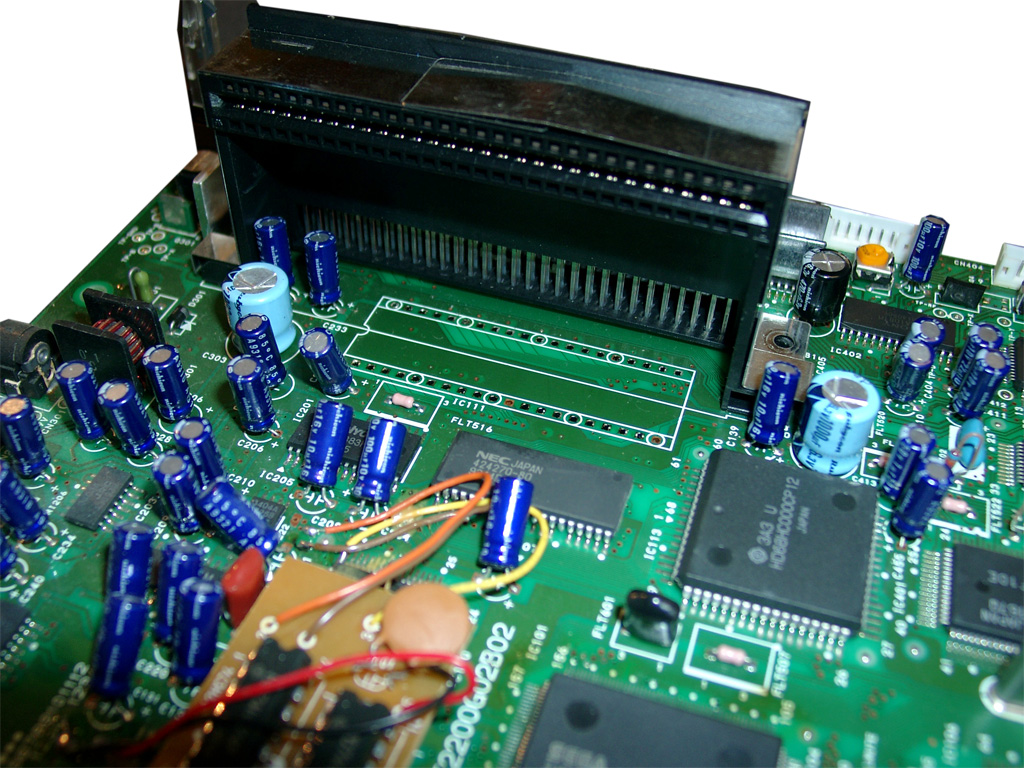
cut the 2 wires left and right (A30, A01)

You will have to pullup Pin 38 and Pin 39 of the Eprom and wire blue and yellow like the following picture
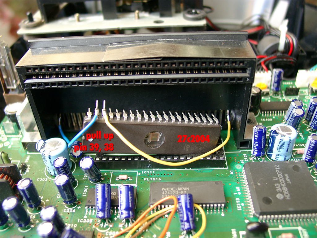
Here you can see the complete eprom attached
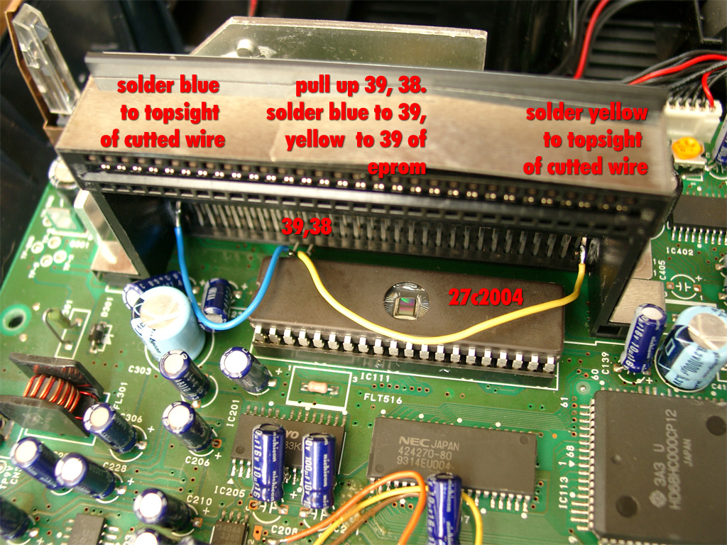
Look here for a video showing how the modification is working (german language)
http://www.youtube.com/watch?v=PYxM5u4DBis
english
Posted in Sega, Switchless Mods | 1 Comment »
Sega Saturn switchless MOD Pal smaller mainbaord
Montag, März 15th, 2010
My second german Saturn for switchless MOD was not the same as the first one.
This one got 2 PCBs inside. A smaller Main PCB and a separate Controller Port PCB.
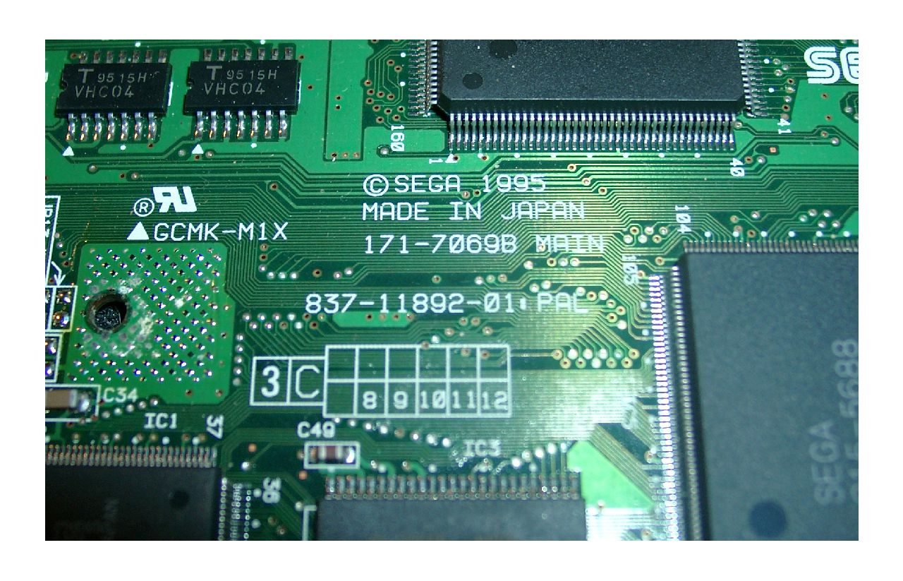
The Mainboard is called: 837-11892-01 PAL.
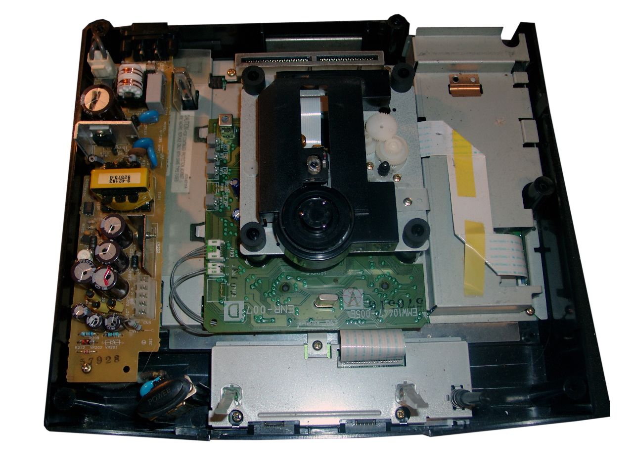
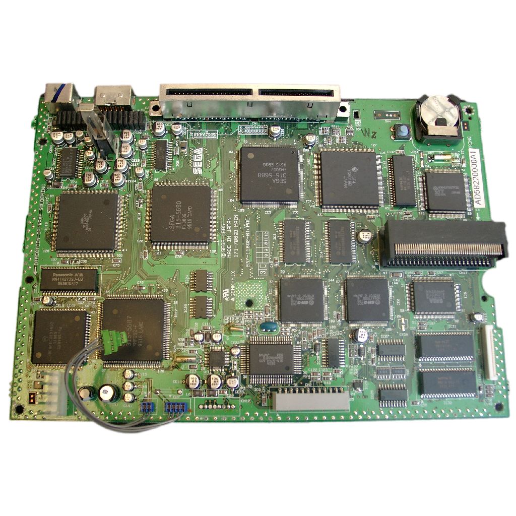
Here you can find the Mainboard Revision on the TOP Side of the Board
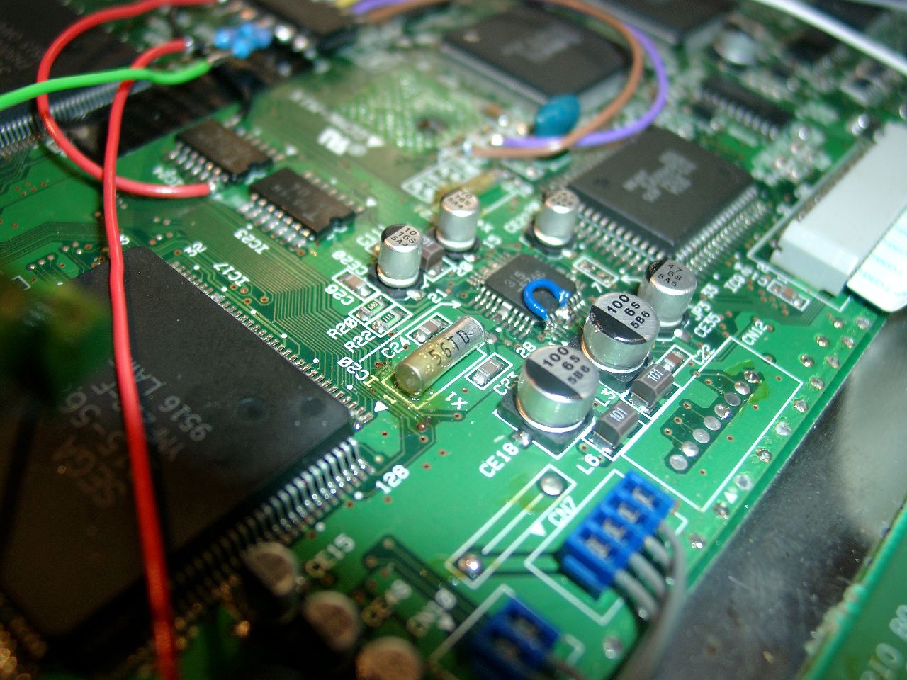
For correct working of the 50/60Hz you have to desolder Pin 1 and pull up pin 1 of IC20.
Then wire it to GND.
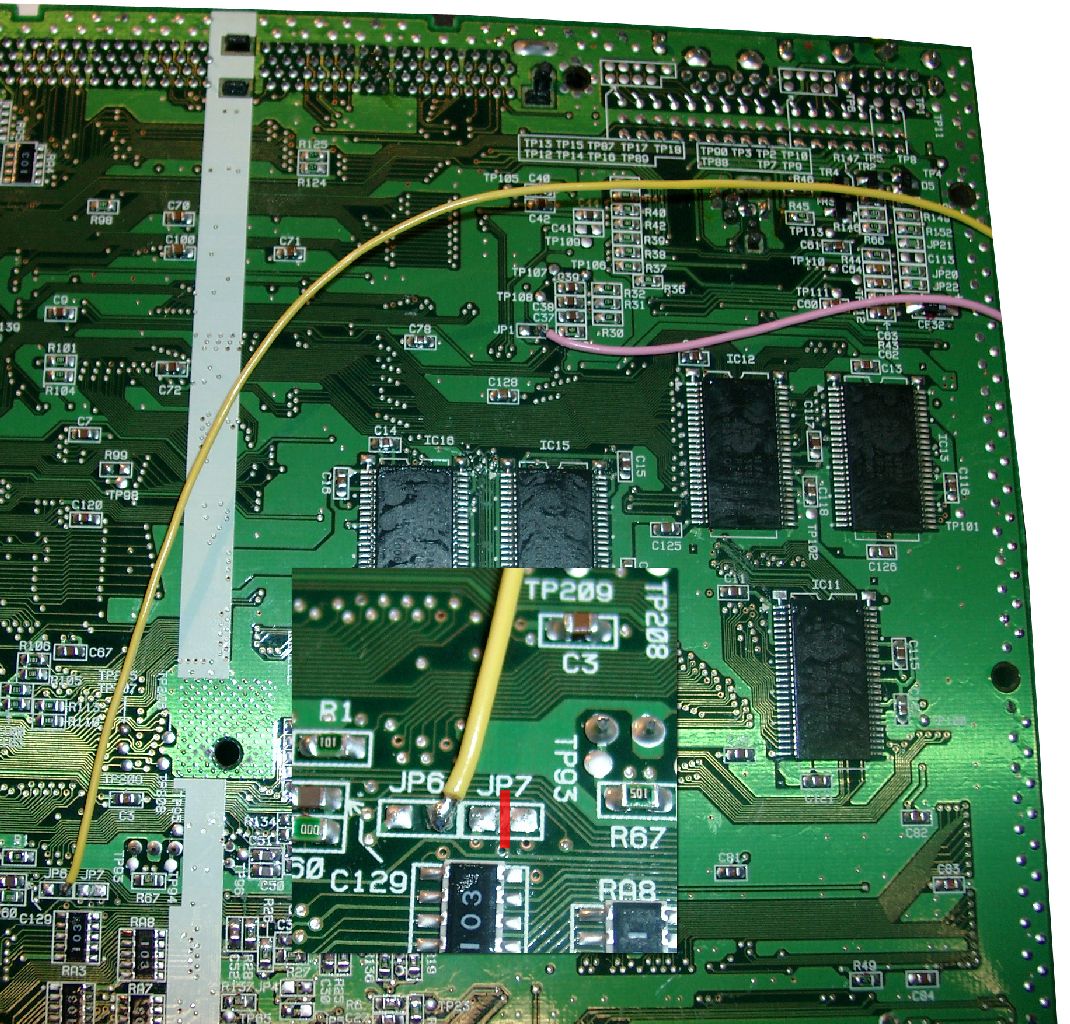
Backsite Mainboard.You need to cut the jumper at JP7 (remove the circuit)
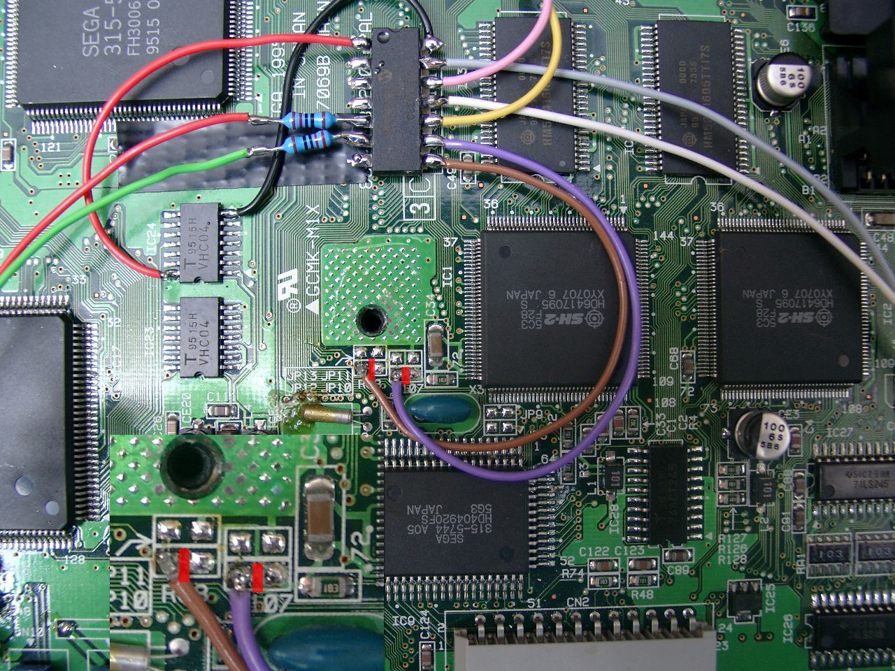
Frontsite of the Mainboard (LED Resistors 220Ohm) PIC 16F630 cut the two red marked circuit pathes between JP12 and JP 10
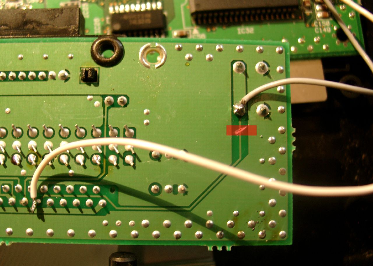
Separate Controller PCB (cut the red marked circuit)
wire colors (upper site grey at the RESET Button, downsite white)
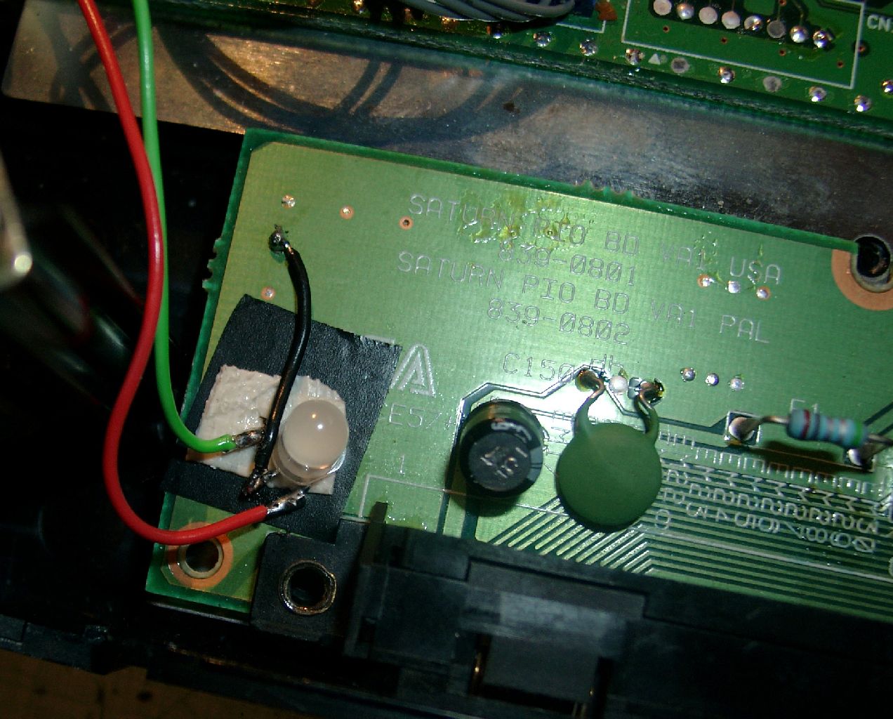
DUO-LED soldering an position at the separate Controller PCB
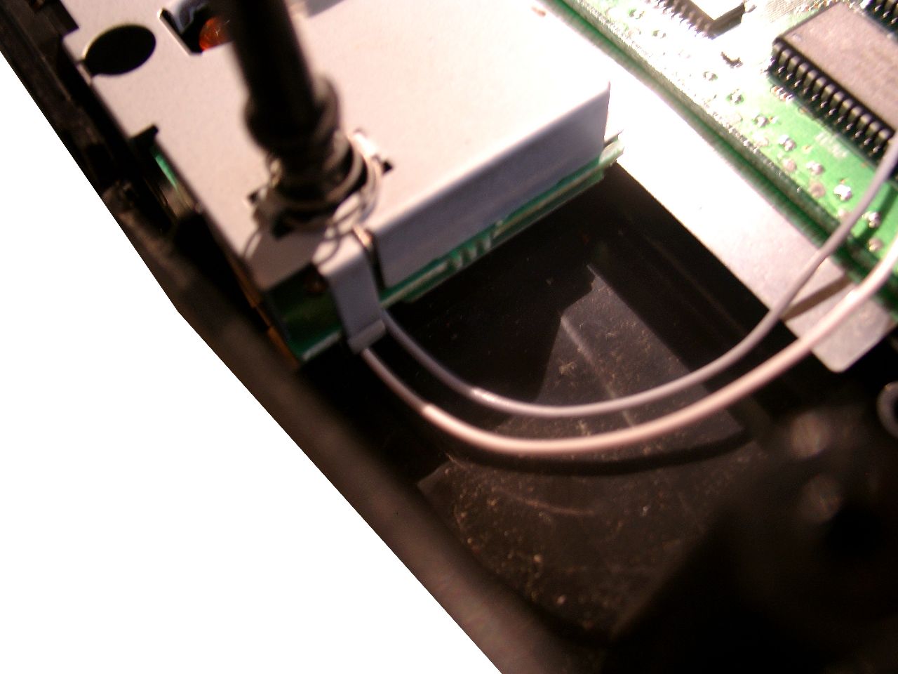
Some more pictures

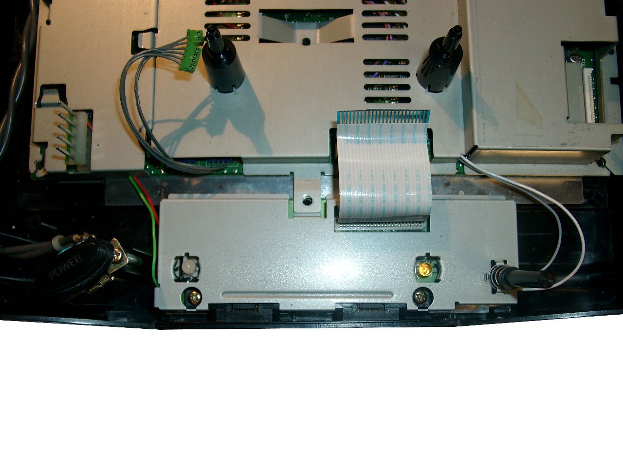
Posted in Sega, Switchless Mods | No Comments »